
Page 108 - Subyek Teknik Mesin - Forsthoffers Best Practice Handbook for Rotating Machinery by William E Forsthoffer
P. 108
Pump Best Practices Best Practice 2 .20
C a s e 1 2 3
N (speed) 3600 rpm 3600 rpm 3600 rpm
C (bearing 3000 3000 3000
dynamic load
factor – lbs)
F (total actual 170 500 1000
bearing load –
lbs)
Condition As designed Additional Additional
soft foot pipe load
forces forces
L-10 life years 25,495 hours 1002 hours 125 hours
Cause of early No early failure specified Excessive Excessive
failure minimum life was soft foot pipe load
exceeded forces forces
Note: use the relationship in Figure 2.20.7 to determine the
bearing L-10 life.
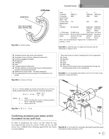
Fig 2.20.5 Radial bearing
Fig 2.20.8 External loads on equipment example (use the
relationship in Figure 2.20.7)
Increased process pipe forces and moments They exert forces in excess of design limits on the components:
Foundation forces (‘soft’ foot, differential settlement) Casing
Fouling or plugging of impeller Bearings
Misalignment Rotor
Unbalance Seals
Rubs Wear rings
Improper assembly clearances The path of the forces is from the external force through the
Thermal expansion of components (loss of cooling medium, casing bearing bracket to the components
excessive operating temperature)
Radial forces (single volute – off design operation)
Poor piping layouts (causing unequal flow distribution to the Fig 2.20.9 How excessive pipe stress and soft foot forces cause
pump) equipment component failure
Fig 2.20.6 Sources of forces
‘B’ or ‘L’ - 10 life is defined as the life in hours that 9 out of 10 ran-
domly selected bearings would exceed in a specific application.
16700 C 3
‘B’ or ‘L’ 10 life =
N F
Where : N = RPM
C = Load in lbs that will result in a bearing element
life of 1, 000, 000 revolutions
F = Actual load in lbs
Fig 2.20.7 ‘B’ or ‘L’ - 10 life
Confirming excessive pipe stress and/or
foundation forces (soft foot)
In order to implement any action, we had better be sure
our suspected root causes are correct. If they are not, we will
always have a difficult time obtaining approval for any future Fig 2.20.10 Force path from excessive discharge flange loadings to
recommendation. the bearing bracket (Courtesy of API)
81