
Page 103 - Subyek Teknik Mesin - Forsthoffers Best Practice Handbook for Rotating Machinery by William E Forsthoffer
P. 103
Pump Best Practices Best Practice 2 .19
Fig 2.19.2 Low flow temperature rise can cause vapor formation
Liquid temperature rise increases by:
Pump head 1
DT ¼ 1
337; 100 C P Pump efficiency
Pump head 1
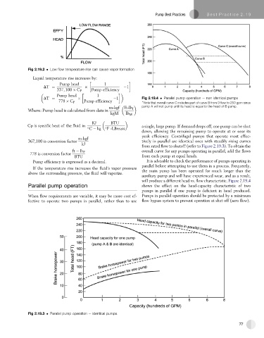
DT ¼ 1 Fig 2.19.4 Parallel pump operation e non identical pumps
778 C P Pump efficiency )
Note that overall curve C includes part of curve B from 0 flow to 250 gpm since
m-kgf ft-lb f pump A will not pump until its head is equal to the head of B pump.
Where: Pump head is calculated from data in
kgM lb M
KJ BTU
Cp is specific heat of the fluid in a single, large pump. If demand drops off, one pump can be shut
C kg F -LBmass
down, allowing the remaining pump to operate at or near its
peak efficiency. Centrifugal pumps that operate most effec-
m-kgf
367,100 is conversion factor tively in parallel are identical ones with steadily rising curves
kJ
from rated flow to shutoff (refer to Figure 2.19.3). To obtain the
ft lb F overall curve for any pumps operating in parallel, add the flows
778 is conversion factor
BTU from each pump at equal heads.
Pump efficiency is expressed as a decimal. It is advisable to check the performance of pumps operating in
parallel before attempting to use them in a process. Frequently,
If the temperature rise increases the fluid’s vapor pressure
above the surrounding pressure, the fluid will vaporize. the main pump has been operated for much longer than the
auxiliary pump and will have experienced wear, and as a result,
will produce a different head vs. flow characteristic. Figure 2.19.4
Parallel pump operation shows the effect on the head-capacity characteristic of two
pumps in parallel if one pump is deficient in head produced.
When flow requirements are variable, it may be more cost ef- Pumps in parallel operation should be protected by a minimum
fective to operate two pumps in parallel, rather than to use flow bypass system to prevent operation at shut off (zero flow).
Fig 2.19.3 Parallel pump operation e identical pumps
77