
Page 101 - Subyek Teknik Mesin - Forsthoffers Best Practice Handbook for Rotating Machinery by William E Forsthoffer
P. 101
Pump Best Practices Best Practice 2 .18
Best Practice 2.18Practice 2.18
Best
Avoid the use of internal type minimum flow bypass valves Lessons Learned
whenever there is a possibility of debris or fouling in the Internal type minimum flow bypass valves have internal
pumped liquid. components that can affect their ability to open at the
Avoid the use of internal-type, minimum flow bypass valves with minimum flow set point. Since they have no external po-
internal orifices and springs for upstream, oil field applications, boiler sition monitoring device, catastrophic consequences can
feed pumps and any other pumps that can come into contact with solid
result in services that can contain solids in the pumped
particles.
liquid.
Use external, minimum flow, bypass valve arrangements that have
Since 1990, several instances of complete, high pressure, boiler feed
a flow transmitter which will open a conventional control valve supplied
pump failure have been observed (where the pump was completely
with properly sized orifice(s).
destroyed, and a new high pressure radial split pump became neces-
External type minimum flow control valves allow operator moni-
sary) in systems that used internal-type minimum flow bypass valves.
toring of valve position and positively prevent valve sticking and failure
to open.
Benchmarks
Since 1990 I have used the best practice of requiring external type
minimum flow bypass control systems with multiple orifice chambers
for all boiler feed water applications.
B.P. 2.18. Supporting Material and low NPSH available applications to determine if an auto-
matic minimum flow bypass system is required.
Automatic minimum flow bypass systems can be either ex-
Minimum flow bypass protection ternal or internal type but must reliably open at the specified set
point. All instruments and valves used must result in repeatable
Depending on the characteristics of the pumped fluid, contin- operation. Failure of a minimum bypass system to function
uous operation under low flow conditions can produce centrif- when required can cause catastrophic pump damage.
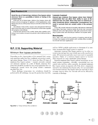
ugal pump damage. Figure 2.18.1 shows the three (3) types of External minimum flow bypass systems incorporate an ex-
minimum flow bypass systems e manual, automatic external ternal sensing transmitter, controller, conventional two way
and automatic internal. As a rule of thumb, minimum flow control valve and flow orifice assembly. An internal minimum
protection should be provided for any pump application that can flow bypass system incorporates all of the above components
continuously operate below the pump vendor’s minimum internal to the minimum flow bypass valve. It is recommended
specified flow rate. that internal minimum flow bypass valves be used only in clean
Pump discharge temperature rise calculations should be pumpage systems where the internals will not be affected by
performed for all multistage, low specific gravity (less than 0.8), corrosion or blockage.
Fig 2.18.1 Pump minimum flow protection
75