
Page 104 - Subyek Teknik Mesin - Forsthoffers Best Practice Handbook for Rotating Machinery by William E Forsthoffer
P. 104
Be st Practice 2 .20 Pump Best Practices
Best Practice 2.20Practice 2.20
Best
Check the pump flange and foundation forces whenever Lessons Learned
blinding and/or installing pumps to ensure that the external Failure to confirm proper pump flange and foundation
forces on the bearings are minimum. forces will lead to low bearing MTBF, and possible safety
Most centrifugal pumps use anti-friction bearings. issues in hot water or hydrocarbon applications.
The life of any type of anti-friction bearing is inversely proportional Many low pump anti-friction MTBF issues (less than 6 months) have
to the cube of the forces on the bearing. As an example, if the forces on been solved by checking and correcting external pipe and foundation
an anti-friction bearing double, the life of the bearing will decrease by forces using the methods noted below.
eight times!
Checking the pipe forces and foundation forces (known as soft Benchmarks
foot), whenever piping is installed or disturbed will ensure that
This best practice has been used since the mid-1980s to optimize
the forces on bearings are acceptable and yield optimum bearing
pump safety and reliability. Bearing MTBFs have been increased from
MTBF.
less than 6 months to greater than 100 months by implementing these
pipe and foundation check methods.
B.P. 2.20. Supporting Material
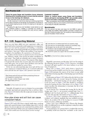
Have you ever been called into your supervisor’soffice and Under the limit on external pipe force (on assembly dwg)
questioned on how to properly install equipment or a component? Under the limit on external pipe moments (on assembly dwg)
All support feet are flat and in the same plane
Have you ever had the experience of installing a component Foundation under all support feet has been leveled (shimmed
(bearing), only to have it fail repeatedly over the following months
if necessary with stainless steel shims)
and became a ‘bad actor’? What is the problem? Your assembly All external pipe(s) and support feet are properly connected
procedures, the installation, the equipment, or the process?
The subject of this chapter is equipment pipe stress and soft
foot. Without a doubt, these factors are prime contributors to Fig 2.20.2 External force design assumptions
‘bad actors’. They both are relatively easy to prove; however,
they can be very difficult to correct. The purpose of this chapter
is to present the reasons why excessive pipe stress and soft foot Hopefully your answer was the rotor. Let’s use the pump in
cause bad actors, how to prove these problems exist and the the following discussion (Figure 2.20.3). However, everything
most cost-effective method to correct them. discussed will apply equally to the steam turbine or any other
Before we can understand how pipe stress and soft foot can type of equipment.
cause equipment component failures, we must know what pipe Please refer to Figure 2.20.5, which shows a typical anti-
stress and soft foot are! Figure 2.20.1 presents these facts. friction bearing that would be used for the pump radial bearing.
Figure 2.20.6 presents the sources of the forces on any radial
and/or thrust bearing regardless of the bearing type (anti-friction
Pipe stress and soft foot exert failure producing forces on or sleeve).
the equipment casing from: For the pump in Figure 2.20.3, please describe the forces that
Top, side or bottom flanges (pipe loads) the designer takes into account during the bearing selection.
Support feet (soft foot) (Remember e anti-friction bearings are not custom designed.)
Circle the forces in Figure 2.20.6 that should be considered
during the bearing selection. Now please refer to Figure 2.20.7
Fig 2.20.1 Pipe stress and soft foot
which describes the relationship to determine the life of any
Naturally, all equipment cases are designed to accommodate anti-friction bearing.
reasonable pipe loads and minimal load due to soft foot. How- As an exercise, let’s determine the bearing life for the fol-
ever, Figure 2.20.2 shows what the equipment designer assumes lowing cases: Case 1 e no excessive external load; Case 2 e
in this regard. additional soft foot load; and Case 3 e additional pipe stress
load. We will note this information in Figure 2.20.8.
In Figure 2.20.8, Case 1 represents a bearing selected in ac-
How pipe stress and soft foot can cause cordance with industry standards that was installed correctly.
component failure That is, the predicted life of the bearing is in excess of 25,000
hours or 3 years’ continuous operation.
Figures 2.20.3 and 2.20.4 show a typical, single stage, overhung Cases 2 and 3 are a different story! Observe the dramatic
pump and a general purpose steam turbine respectively. In both effect of additional forces on the equipment casing from either
figures, the process pipes are not connected. If, in addition, both soft foot or piping forces.
the pump and steam turbine were not coupled or bolted to their If your manager or an operator had to complete this exercise,
bases, what would cause the load (force) on the bearings? he probably would have listed the ‘machinist’ as the cause of
78