
Page 110 - Subyek Teknik Mesin - Forsthoffers Best Practice Handbook for Rotating Machinery by William E Forsthoffer
P. 110
Pump Best Practices Best Practice 2 .20
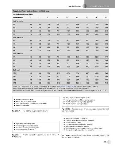
Table 2.20.2 Nozzle loadings (Courtesy of API) (US units)
Nominal size of flange (NPS)
Force/moment 2 3 4 6 8 10 12 14 16
Each top nozzle
FX 160 240 320 560 850 1200 1500 1600 1900
FY 130 200 260 460 700 1000 1200 1300 1500
FZ 200 300 400 700 1100 1500 1800 2000 2300
FR 290 430 570 1010 1560 2200 2600 2900 3300
Each side nozzle
FX 160 240 320 560 850 1200 1500 1600 1900
FY 200 300 400 700 1100 1500 1800 2000 2300
FZ 130 200 260 460 700 1000 1200 1300 1500
FR 290 430 570 1010 1560 2200 2600 2900 3300
Each end nozzle
FX 200 300 400 700 1100 1500 1800 2000 2300
FY 160 240 320 560 850 1200 1500 1600 1900
FZ 130 200 260 460 700 1000 1200 1300 1500
FR 290 430 570 1010 1560 2200 2600 2900 3300
Each nozzle
MX 340 700 980 1700 2600 3700 4500 4700 5400
MY 170 350 500 870 1300 1800 2200 2300 2700
MZ 260 530 740 1300 1900 2800 3400 3500 4000
MR 460 950 1330 2310 3500 5000 6100 6300 7200
Note 1: F [ force in pounds; M [ movement in foot pounds; R [ resultant. See Figures 2.20.11 and 2.20.12 for orientation of nozzle loads (X, Y and Z).
th
Note 2: Coordinate system has been changed from API Standard 610, 7 edition, convention to ISO 1503 convention.
Note 3: Each value shown below indicates a range from minus that value to plus that value; for example 160 indicates a range from e160 to þ160.
Using equipment as a ‘pipe support’
Process condition change Improper installation of fixed spring supports
Piping and foundation change Poor foundation and/or grout preparation
‘Unit’ (driven, driver, transmission, auxiliaries) Poor foundation and/or grout pour
Ambient conditions
Fig 2.20.15 Possible causes for excessive pipe stress and/or soft
Fig 2.20.13 The rotating equipment environment foot (construction)
Settling pipe support foundations
Cracked grout and/or foundation (concrete)
Locked spring supports
Pipe stress calculation error
Improperly installed new spring supports
Improper spring hanger selection Shim corrosion under pipe supports
Improper soil analysis assumptions Shim corrosion between equipment feet and baseplate
Improper foundation design Shims vibrating loose under pipe supports
Fig 2.20.14 Possible causes for excessive pipe stress and/or soft Fig 2.20.16 Possible root causes for excessive pipe stress and/or
foot (design) soft foot (plant conditions)
83