
Page 146 - Subyek Teknik Mesin - Forsthoffers Best Practice Handbook for Rotating Machinery by William E Forsthoffer
P. 146
Be st Practice 3 .4 Compressor Best Practices
Frame and running gear usual to use an epoxy grout, since they provide high bond
strengths and are oil resistant. All reciprocating baseplates
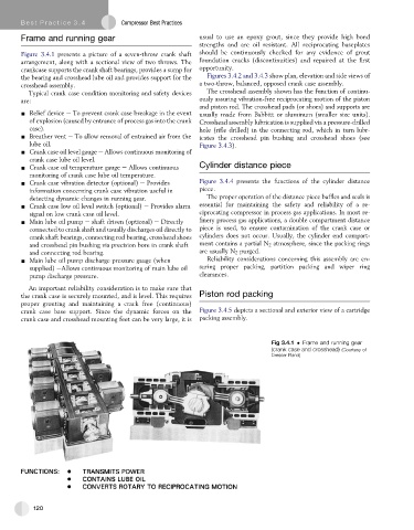
Figure 3.4.1 presents a picture of a seven-throw crank shaft should be continuously checked for any evidence of grout
arrangement, along with a sectional view of two throws. The foundation cracks (discontinuities) and repaired at the first
crankcase supports the crank shaft bearings, provides a sump for opportunity.
the bearing and crosshead lube oil and provides support for the Figures 3.4.2 and 3.4.3 show plan, elevation and side views of
crosshead assembly. a two-throw, balanced, opposed crank case assembly.
Typical crank case condition monitoring and safety devices The crosshead assembly shown has the function of continu-
are: ously assuring vibration-free reciprocating motion of the piston
and piston rod. The crosshead pads (or shoes) and supports are
- Relief device e To prevent crank case breakage in the event usually made from Babbitt or aluminum (smaller size units).
of explosion (caused by entrance of process gas into the crank Crosshead assembly lubrication is supplied via a pressure-drilled
case). hole (rifle drilled) in the connecting rod, which in turn lubr-
- Breather vent e To allow removal of entrained air from the icates the crosshead pin bushing and crosshead shoes (see
lube oil. Figure 3.4.3).
- Crank case oil level gauge e Allows continuous monitoring of
crank case lube oil level.
- Crank case oil temperature gauge e Allows continuous Cylinder distance piece
monitoring of crank case lube oil temperature.
- Crank case vibration detector (optional) e Provides Figure 3.4.4 presents the functions of the cylinder distance
information concerning crank case vibration useful in piece.
detecting dynamic changes in running gear. The proper operation of the distance piece baffles and seals is
- Crank case low oil level switch (optional) e Provides alarm essential for maintaining the safety and reliability of a re-
signal on low crank case oil level. ciprocating compressor in process gas applications. In most re-
- Main lube oil pump e shaft driven (optional) e Directly finery process gas applications, a double compartment distance
connected to crank shaft and usually discharges oil directly to piece is used, to ensure contamination of the crank case or
crank shaft bearings, connecting rod bearing, crosshead shoes cylinders does not occur. Usually, the cylinder end compart-
and crosshead pin bushing via precision bore in crank shaft ment contains a partial N 2 atmosphere, since the packing rings
and connecting rod bearing. are usually N 2 purged.
- Main lube oil pump discharge pressure gauge (when Reliability considerations concerning this assembly are en-
supplied) eAllows continuous monitoring of main lube oil suring proper packing, partition packing and wiper ring
pump discharge pressure. clearances.
An important reliability consideration is to make sure that
the crank case is securely mounted, and is level. This requires Piston rod packing
proper grouting and maintaining a crack free (continuous)
crank case base support. Since the dynamic forces on the Figure 3.4.5 depicts a sectional and exterior view of a cartridge
crank case and crosshead mounting feet can be very large, it is packing assembly.
Fig 3.4.1 Frame and running gear
(crank case and crosshead) (Courtesy of
Dresser Rand)
120