
Page 171 - Subyek Teknik Mesin - Forsthoffers Best Practice Handbook for Rotating Machinery by William E Forsthoffer
P. 171
Compressor Best Practices Best Practice 3 .11
B.P. 3.10. Supporting Material that the objective of the machinery vendor is to design the
machinery safely and properly for the warranty period, while
The use of these head per impeller limits, prior to the priced offering the lowest possible price. The objective of the operating
proposal submission, allows the vendors to re-select and defi- plant is to produce maximum product revenue for the life of the
nitely meet these requirements. Do not be persuaded by ex- process unit (20 plus years). Today (2010), unspared centrifugal
perience charts, etc. Remember most importantly (see BP 1.1) compressor downtime can exceed $5MM/day.
Best Practice 3.11Practice 3.11Practice 3.11
Best
Best
Require centrifugal compressor head rise to be a minimum considered, based on stated vendor experience and possible discus-
of 5% in order to prevent control and protection system sion with end users.
issues in the field.
Centrifugal compressor head rise is defined as the head at surge Lessons Learned
condition divided by the head at rated point. I have been involved with many surge problems related to
The lower is the head rise, the more rapid a change in flow for flat (low head rise) performance curves. Flat compressor
a change in the head required by the process. characteristic curves require rapid surge systems reaction
Review each proposed impeller head rise during the pre-bid phase, times to prevent surge from occurring.
and require the vendor to re-select any impellers that have a head rise
that is less than 5%. Benchmarks
Note that for heavy gas applications, greater than 40 molecular
weight, this may be difficult and in those cases, acceptance of the This best practice has been used since 2000, and has resulted in op-
timum compressor safety and trouble free operation (reliability above
highest impeller head rise available from the vendor will have to be
99.7%) and no continuing surge system problems.
B.P. 3.11. Supporting Material compressor’s flow rate decreases from rated point to surge point
is on the order of only 10%, it can be seen that a small change in
The factors involved gas density can result in a significant flow reduction and possibly
compressor surge.
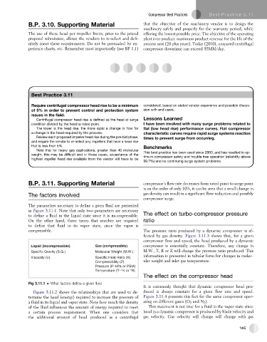
The parameters necessary to define a given fluid are presented
in Figure 3.11.1. Note that only two parameters are necessary
to define a fluid in the liquid state since it is incompressible. The effect on turbo-compressor pressure
On the other hand, three times that number are required ratio
to define that fluid in its vapor state, since the vapor is
compressible. The pressure ratio produced by a dynamic compressor is af-
fected by gas density. Figure 3.11.3 shows that, for a given
compressor flow and speed, the head produced by a dynamic
Liquid (incompressible) Gas (compressible) compressor is essentially constant. Therefore, any change in
Specific Gravity (S.G.) Molecular Weight (M.W.) M.W., T, K or Z will change the pressure ratio produced. This
information is presented in tabular form for changes in molec-
Viscosity ( ) Specific Heat Ratio (K)
Compressibility (Z) ular weight and inlet gas temperature.
Pressure (P–kPa or PSIA)
Temperature (T–°K or °R)
The effect on the compressor head
Fig 3.11.1 What factors define a given fluid
It is commonly thought that dynamic compressor head pro-
Figure 3.11.2 shows the relationships that are used to de- duced is always constant for a given flow rate and speed.
termine the head (energy) required to increase the pressure of Figure 3.11.4 presents this fact for the same compressor oper-
a fluid in its liquid and vapor state. Note how much the density ating on different gases (O 2 and N 2 ).
of the fluid influences the amount of energy required to meet This statement is not true for a fluid in the vapor state since
a certain process requirement. When one considers that head in a dynamic compressor is produced by blade velocity and
the additional amount of head produced as a centrifugal gas velocity. Gas velocity will change will change with gas
145