
Page 173 - Subyek Teknik Mesin - Forsthoffers Best Practice Handbook for Rotating Machinery by William E Forsthoffer
P. 173
Compressor Best Practices Best Practice 3 .11
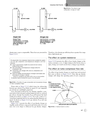
Fig 3.11.4 The effect of gas
composition change on head
density since a gas is compressible. These facts are presented in Therefore, a low density gas will always have a greater flow range
Figure 3.11.5. than a high density gas.
The effect on system resistance
The assumption that compressor head remains constant for a given
flow with gas composition and temperature changes is not true Figure 3.11.8 presents the effect of gas density change on the
because: system resistance curve. A slight change in the friction drop in
Head is generated by impeller tip speed and exit velocity pipes, fittings and vessels results from a change in gas density.
relative to the blade
Gas composition and temperature changes affect the
compression ratio The effect on turbo-compressor flow rate
Volume flow rate changes with pressure, temperature and
compressibility The effect of gas density changes on actual mass and standard
Since the impeller exit area isfixed, a change in exit volume rate flow rates is shown in Figure 3.11.9. Note that gas density
will produce a change in velocity changes will change the operating point of each compressor
Note: For changes on the order of 20%, it is common practice
to assume head is constant for a given flow and speed
Fig 3.11.5 The effect of a gas composition and temperature change
on turbo-compressor head
Please refer to Figure 3.11.6 which shows the relationship
between gas velocity (V rel ) blade tip speed (U) and tangential
gas velocity in a centrifugal compressor.
Since the head produced by any dynamic impeller is pro-
portional to blade tip speed and gas tangential velocity, reduced
gas velocity through the impeller (V rel ) will increase the head
produced as shown in Figure 3.11.6. This is the result of in-
creased gas tangential velocity for a given impeller diameter and
speed. As shown in Figure 3.11.5, gas velocity (V rel ) will vary
with gas density.
Figure 3.11.7 presents the effect of gas density changes on
impeller produced head, surge point and choke point. It can be
seen that curve shape is influenced by gas density changes. Fig 3.11.6 Head produced a (U)(V T )
147