
Page 178 - Subyek Teknik Mesin - Forsthoffers Best Practice Handbook for Rotating Machinery by William E Forsthoffer
P. 178
Be st Practice 3 .13 Compressor Best Practices
Table 3.13.1 Facts and relationships (energy). At the tips of the vanes there are two velocities that
are present: the blade tip velocity, identified as U, and the ve-
- A vector describes magnitude and direction / locity relative to the blade, identified as V REL .
The blade tip velocity is the function of the diameter of the
DN ðDÞðNÞ
Tip speed V ¼ US units blade and the blade rotational speed. The velocity relative to the
19; 108 229
blade (V REL ) is a function of the area between the blades, the flow
Flow related to velocity Q ¼ AV [‘Q’ ¼ (A)(V)(60) ]
rate at that location and the angle of the blade at the discharge of
- Flow related to conditions P l T f Z f the impeller. Summing these two velocities, the resultant or
(compressible flow) Q F Q l P f T l Z l absolute velocity defines the magnitude and the direction of the
gas as it exits the blade. For this discussion, we assume that the
Where U ¼ Tip velocity (m/sec or ft/sec) f ¼ Final condition
velocity relative to the blade exactly follows the blade angle; that
2
D ¼ Diameter (mm or in ) l ¼ Initial condition is, the slip is equal to zero. This assumption can safely be used
since it will not impact the final conclusion of our discussion.
N ¼ Speed (rpm) P ¼ Pressure (kPa or PSIA)
3
3
Q ¼ Flow rate (m /hr or ft /min) T ¼ Temperature ( Kor R) Impeller discharge velocities
K ¼ C þ 273
2
2
A ¼ Area (m or ft ) R ¼ F þ 460 If we now resolve the absolute velocity noted in Figure 3.13.4
(R) into its x and y components, the x axis projection of the
V ¼ Velocity (m/sec or ft/sec) Z ¼ Compressibility
component is the tangential velocity of the gas at the impeller
discharge (refer to Figure 3.13.5). Euler’s energy equation states
‘The energy created by any turbo machine is proportional to the
product of the tip speed and the tangential velocity’.
that the relationships presented are in British units. Metric units Let us now assume that the head required by the process
are not presented in this section, but can be easily derived re- changes such that the flow V REL through the impeller reduces.
ferring to appropriate conversion tables. Referring to Figure 3.13.6 let us again examine the discharge
velocity to see what happens at this reduced flow condition.
Impeller with side plate removed Assuming that the rotor speed is constant, it can be seen that
the value of the tip speed does not change, since it is a function
of impeller diameter and shaft speed.
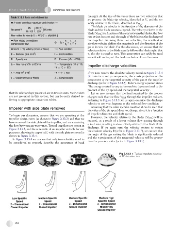
To begin our discussion, assume that we are operating at the However, the velocity relative to the blades (V REL ) will be
impeller design point (as shown in Figure 3.13.3) and that we
have removed the side plate of the impeller, and are examining reduced, as a result of a lower volume flow passing through
the flow between any two vanes. Typical impellers are shown in a fixed area, resulting in a low velocity relative to the blade at the
Figure 3.13.3, and the schematic of an impeller suitable for our discharge. If we again sum the velocity vectors to obtain
purposes, showing its upper half, with the side plate removed is the absolute velocity R (refer to Figure 3.13.7), we can see that
shown in Figure 3.13.4. the angle of the gas exiting the blade is significantly reduced
In Figure 3.13.4 we can see that only two velocities need to and the x projection of the tangential velocity will be greater
be considered to properly describe the generation of head than the previous value (refer to Figure 3.13.8).
Fig 3.13.3 Typical impellers (Courtesy
of IMO Industries, Inc.)
152