
Page 182 - Subyek Teknik Mesin - Forsthoffers Best Practice Handbook for Rotating Machinery by William E Forsthoffer
P. 182
Be st Practice 3 .13 Compressor Best Practices
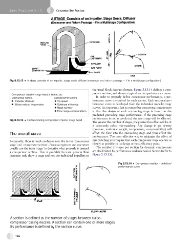
Fig 3.13.12 A stage consists of an impeller, stage seals, diffuser (crossover and return passage e if in a multistage configuration)
the usual block diagram format. Figure 3.13.14 defines a com-
pressor section, and shows a typical section performance curve.
Compressor impeller stage head is limited by:
In order to properly define compressor performance, a per-
Mechanical factors Aerodynamic factors
formance curve is required for each section. Each sectional per-
Impeller stresses Tip speed
Blade natural frequencies Optimum efficiency formance curve is developed from the individual impeller stage
Mach number curves. An important fact to remember concerning compressors
Flow range considerations is that the design of each succeeding stage is based on the
predicted preceding stage performance. If the preceding stage
performance is not as predicted, the next stage will be affected.
Fig 3.13.13 Factors limiting compressor impeller stage head
The greater the number of stages, the greater this effect will be. It
is commonly called mis-matching. Any change in gas density
(pressure, molecular weight, temperature, compressibility) will
The overall curve affect the flow into the succeeding stage and thus affect the
performance. The most effective way to minimize the effect of
mis-matching is to require that each compressor stage operate as
Frequently, there is much confusion over the terms ‘compressor
stage’ and ‘compressor section’. Process engineers and operators closely as possible to its design or best efficiency point.
The number of stages per section for dynamic compressors
usually use the term ‘stage’ to describe what properly is termed
a compressor section. This is probably because process flow are also limited by performance and mechanical factors (refer to
diagrams only show a stage and not the individual impellers in Figure 3.13.15).
Fig 3.13.14 Compressor section - definition/
performance curve
156