
Page 185 - Subyek Teknik Mesin - Forsthoffers Best Practice Handbook for Rotating Machinery by William E Forsthoffer
P. 185
Compressor Best Practices Best Practice 3 .14
Best
Best Practice 3.14Practice 3.14
Positively define compressor fouling (debris accumulation Lessons Learned
on impellers and gas passages) by performance calcula- Failure to monitor performance and phase angle of vibra-
tions and phase angle changes (heavy spot of unbalance). tion has caused many compressor disassemblies when the
Performance deterioration (efficiency and head reduction) can be fouling could have been removed by cleaning the com-
caused by: pressor internals without disassembly.
Gas density changes (see Best Practice 3.13) Performance deterioration usually dictates that the compressor
Internal stage seal wear must be disassembled. This may in fact be the case, but, if rotor phase
Assembly error angle is not monitored, a fouled compressor may be disassembled
Fouling unnecessarily, causing significant amounts of downtime (3 e7 days)
and corresponding loss of revenue.
Fouling will have the greatest effect on compressor efficiency, re-
ducing its value by 10% or more. Fouling can also be determined by
monitoring phase angle change on the rotor since fouling on the im- Benchmarks
peller will break off irregularly causing unbalance and change of the The best practice of using on line and off line washing in upstream,
heavy spot (phase angle change). downstream chemical and refinery compressor applications has been
If fouling is the cause of the performance deterioration, it can be used since the 1980s to prevent compressor disassembly during
usually corrected without compressor disassembly, thus saving a turnaround.
downtime and revenue losses.
B.P. 3.14. Supporting Material The mechanism of fouling
The material contained in this section will aid in preventing and As mentioned earlier, one can reduce any blade row or impeller
correcting fouling. It is based on our experience since the 1980s, to a series of equivalent orifices. Flow is a function of area and
which has prevented many unnecessary compressor velocity.
disassemblies. Whenever any blade row or impeller is designed, the designer
Thus far, we have investigated the cause of the compressor sets inlet and discharge blade areas such that optimum velocities
curve, that is, the method in which energy is produced in any relative to the blade will be achieved at each location. By a series
blade row or impeller. Energy is produced by the change in two of tests and experience, designers have defined optimum relative
velocities, namely the difference between inlet and discharge velocity rather well. Therefore the resulting inlet and discharge
velocity relative to the blade and the change between inlet blade areas will produce optimum velocities and corresponding opti-
tip speed and discharge blade tip speed. In this section we will mum impeller efficiencies. If, however, the areas were to change,
explore what will happen to the energy production of a blade and flow passages were to become rough and non-continuous, an
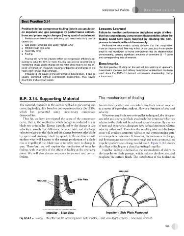
row or impeller if that blade row or impeller were to change in impeller performance change would result. Figure 3.14.1 shows
area. Therefore, we will explain the mechanism of impeller the effect of fouling on a closed centrifugal impeller.
fouling, with examples of the effect of fouling at the operating Impeller fouling is defined as the accumulation of debris in
point. We will also discuss measures to prevent and correct the impeller or blade passage, which reduces the flow area and
fouling. roughens the surface finish. The distribution of the foulant on
Fig 3.14.1 Fouling e the effect on the operating point. Left: impeller e side view. Right: impeller e side plate removed
159