
Page 186 - Subyek Teknik Mesin - Forsthoffers Best Practice Handbook for Rotating Machinery by William E Forsthoffer
P. 186
Be st Practice 3 .14 Compressor Best Practices
Fig 3.14.2 Impeller with side plate removed
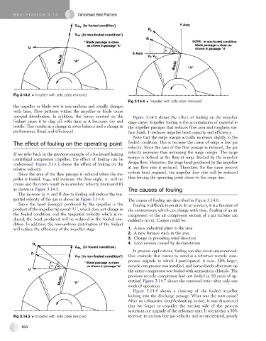
Fig 3.14.4 Impeller with side plate removed
the impeller or blade row is non-uniform and usually changes
with time. Flow patterns within the impeller or blade cause
unequal distribution. In addition, the forces exerted on the Figure 3.14.5 shows the effect of fouling on the impeller
foulant cause it to chip off with time as it becomes dry and stage curve. Impeller fouling is the accumulation of material in
brittle. This results in a change in rotor balance and a change in the impeller passages that reduces flow area and roughens sur-
performance (head and efficiency). face finish. It reduces impeller head capacity and efficiency.
Note that the surge margin actually increases slightly in the
The effect of fouling on the operating point fouled condition. This is because the cause of surge is low gas
velocity. Since the area of the flow passage is reduced, the gas
velocity increases thus increasing the surge margin. The surge
If we refer back to the previous example of a backward leaning
centrifugal compressor impeller, the effect of fouling can be margin is defined as the flow at surge divided by the impeller
understood. Figure 3.14.2 shows the effect of fouling on the design flow. However, the stage head produced by the impeller
relative velocity. at any flow rate is reduced. Therefore, for the same process
Since the area of the flow passage is reduced when the im- system head required, the impeller flow rate will be reduced
peller is fouled, V REL will increase, the flow angle, f, will in- thus forcing the operating point closer to the surge line.
crease and therefore result in an absolute velocity (increased R)
as shown in Figure 3.14.3. The causes of fouling
The increase in f and R due to fouling will reduce the tan-
gential velocity of the gas as shown in Figure 3.14.4. The causes of fouling are described in Figure 3.14.6.
Since the head (energy) produced by the impeller is the Fouling is difficult to predict. In air services, it is a function of
product of the impeller tip speed “U”, which does not change in the environment which can change with time. Fouling of an air
the fouled condition, and the tangential velocity which is re- compressor or the air compressor section of a gas turbine can
duced, the head produced will be reduced in the fouled con- suddenly occur. Causes could be:
dition. In addition, the non-uniform distribution of the foulant
will reduce the efficiency of the impeller stage. 1. A new industrial plant in the area
2. A new furnace stack in the area
3. Change in prevailing wind direction
4. Land erosion caused by de-forestation
In process applications, fouling can also occur unannounced.
One example that comes to mind is a reformer recycle com-
pressor upgrade in which I participated. A new, 30% larger,
recycle compressor was installed, and immediately after start-up
the entire compressor was fouled with ammonium chloride. The
previous recycle compressor had not fouled in 10 years of op-
eration! Figure 3.14.7 shows the removed rotor after only one
week of operation.
Figure 3.14.8 shows a close-up of the fouled impeller
looking into the discharge passage. What was the root cause?
After an exhaustive troubleshooting period, it was discovered
that we forgot to consider the suction side of the process
system in our upgrade of the reformer unit. It seems that a 30%
Fig 3.14.3 Impeller with side plate removed increase in suction line gas velocity and an undersized, poorly
160