
Page 180 - Subyek Teknik Mesin - Forsthoffers Best Practice Handbook for Rotating Machinery by William E Forsthoffer
P. 180
Be st Practice 3 .13 Compressor Best Practices
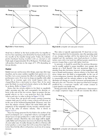
Fig 3.13.9 Radial blading Fig 3.13.10 Impeller with side plate removed
This value is typically approximately 3% head rise or less.
Head rise is defined as the head produced by the impeller at
the low flow operating point divided by the head produced by This is an important fact to remember, since the operating point
the impeller at the impeller design point. Today, the industry of any dynamic machine will be the intersection of the head
prefers backward leaning impellers with an external or exit required and the machinery curve head produced. A charac-
blade angle of approximately 40 to 50 degrees. This blade angle teristic curve with a low head rise will have greater sensitivity to
will produce head rises in the range of 5e15% depending on process changes than a curve with higher head rise.
the gas density. In summary, it should be noted that the previous discussion
can be equally applied to pump impellers, since pumps also
operate on a fluid (liquid). One very important thing to re-
Radial
member from this discussion, however, is that regardless of the
Radial vanes are used in some older design, open type, first stage type of liquid used in pumps, velocity relative to the blade will
impellers, and in some modern impellers that operate at a very never change since the fluid is incompressible. In the case of
low flow. Let us now examine the effect of a radial blade on the a turbo-compressor, however, this will not be true, since the gas
performance curve. If we were to design an impeller with radial is compressible and the velocity relative to the blades at the
blades let us examine again what would happen when we discharge will change as a result of pressure and temperature of
changed flows from a rated point to a lower flow. At the rated that gas at the exit. Therefore the statement that head (energy)
point the blade tip speed and velocity relative to the blade will produced by a compressor impeller will remain constant at
be as shown. Refer to Figure 3.13.9. a given speed is not totally true.
Notice that the velocity relative to the blade is completely Having previously discussed the performance characteristics
radial, assuming zero slip, and consequently the absolute ve- of a single compressor stage, we will now examine the effects
locity is the sum of the two vectors. Again we project the tan-
gential velocity on the x axis projection from the absolute
velocity and note its value as shown in Figure 3.13.10.
At a lower flow, tip speed will remain constant (assuming
constant shaft speed) and the relative velocity will decrease as
in thecaseofthebackward leaningblade. However, note that
since the relative velocity follows the radial blade path, the
magnitude of the tangential velocity remains constant regard-
less of the value of relative velocity. This is shown in
Figure 3.13.11.
Since the energy generated by the blade is the product of tip
speed (unchanged) and a tangential velocity (unchanged) the
design head (energy) produced in a radial impeller will remain
essentially constant. Therefore, the curve shape will be signifi-
cantly flatter and will possess much less of a head rise than that
of a non radial vane. In reality though, the effects of friction will
in fact produce a curve shape that will increase from high flows
to low flows but the effects will produce much less of an energy
increase. Fig 3.13.11 Impeller with side plate removed
154