
Page 177 - Subyek Teknik Mesin - Forsthoffers Best Practice Handbook for Rotating Machinery by William E Forsthoffer
P. 177
Compressor Best Practices Best Practice 3 .13
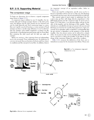
B.P. 3.13. Supporting Material the important concept of an equivalent orifice. Refer to
Figure 3.13.2.
Given any impeller configuration, specific areas can be re-
The compressor stage
duced to equivalent orifices: the eye or inlet area, the discharge
area between any two vanes, the eye seal and the hub or shaft seal.
To begin our discussion, let us observe a typical compressor This concept makes it much easier to understand that, for
stage shown in Figure 3.13.1. agiven area, gas flow will change directly proportional to the
A compressor stage is defined as one (1) impeller, the sta- differential pressure and the compressor stage. It can be seen in
tionary inlet and discharge passages known as the inlet guide Figure 3.13.2 that there is an optimum design velocity for the
vanes, the diffuser and the seals, namely the eye labyrinth seal inlet of the impeller and the discharge of the impeller. These
and the shaft labyrinth seal. Each compressor stage at a given velocities are controlled by selection of a proper inlet eye area and
flow and impeller speed will produce a certain amount of head discharge area based on the impeller flow requirement. Again, the
(energy) and have a specific stage efficiency. It can be observed
concept of an equivalent orifice is helpful in understanding that
that any dynamic curve (turbo-compressor or pump) has the the gas velocity is dependent on the geometry of the specific
characteristic of producing increased energy only at a lower fluid
impeller. Also, the process system can be reduced to a simple
flow assuming the inlet speed and the inlet gas angle are orifice. In any process, the suction discharge sides of the process
constant. can be conceived as orifices placed either at the inlet or the dis-
Before we continue, a few important facts and relationships charge of the compressor flanges for a given flow condition.
need to be presented. These relationships are: the definition of Table 3.13.1 presents the definitions of the facts and re-
a vector, tip speed, flow as a function of velocity and flow related lationships necessary for the discussion that follows. Please note
to conditions and the concept of actual flow. In addition, there is
Fig 3.13.1 The compressor stage and
characteristic curve
Fig 3.13.2 Reduce it to an equivalent orifice
151