
Page 192 - Subyek Teknik Mesin - Forsthoffers Best Practice Handbook for Rotating Machinery by William E Forsthoffer
P. 192
Be st Practice 3 .15 Compressor Best Practices
Fig 3.15.4 The compressor stage and
characteristic curve
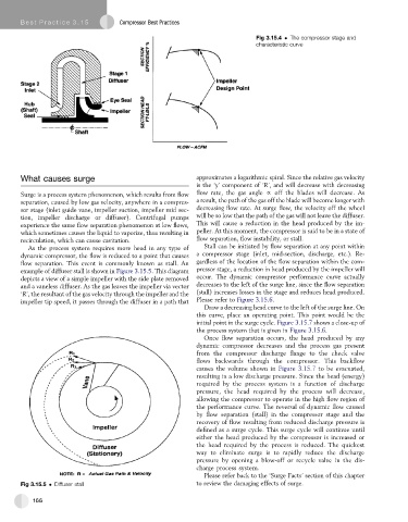
What causes surge approximates a logarithmic spiral. Since the relative gas velocity
is the ‘y’ component of ‘R’, and will decrease with decreasing
Surge is a process system phenomenon, which results from flow flow rate, the gas angle f off the blades will decrease. As
separation, caused by low gas velocity, anywhere in a compres- a result, the path of the gas off the blade will become longer with
sor stage (inlet guide vane, impeller suction, impeller mid sec- decreasing flow rate. At surge flow, the velocity off the wheel
tion, impeller discharge or diffuser). Centrifugal pumps will be so low that the path of the gas will not leave the diffuser.
experience the same flow separation phenomenon at low flows, This will cause a reduction in the head produced by the im-
which sometimes causes the liquid to vaporize, thus resulting in peller. At this moment, the compressor is said to be in a state of
recirculation, which can cause cavitation. flow separation, flow instability, or stall.
As the process system requires more head in any type of Stall can be initiated by flow separation at any point within
dynamic compressor, the flow is reduced to a point that causes a compressor stage (inlet, mid-section, discharge, etc.). Re-
flow separation. This event is commonly known as stall. An gardless of the location of the flow separation within the com-
example of diffuser stall is shown in Figure 3.15.5. This diagram pressor stage, a reduction in head produced by the impeller will
depicts a view of a simple impeller with the side plate removed occur. The dynamic compressor performance curve actually
and a vaneless diffuser. As the gas leaves the impeller via vector decreases to the left of the surge line, since the flow separation
‘R’, the resultant of the gas velocity through the impeller and the (stall) increases losses in the stage and reduces head produced.
impeller tip speed, it passes through the diffuser in a path that Please refer to Figure 3.15.6.
Draw a decreasing head curve to the left of the surge line. On
this curve, place an operating point. This point would be the
initial point in the surge cycle. Figure 3.15.7 shows a close-up of
the process system that is given in Figure 3.15.6.
Once flow separation occurs, the head produced by any
dynamic compressor decreases and the process gas present
from the compressor discharge flange to the check valve
flows backwards through the compressor. This backflow
causes the volume shown in Figure 3.15.7 to be evacuated,
resulting in a low discharge pressure. Since the head (energy)
required by the process system is a function of discharge
pressure, the head required by the process will decrease,
allowing the compressor to operate in the high flow region of
the performance curve. The reversal of dynamic flow caused
by flow separation (stall) in the compressor stage and the
recovery of flow resulting from reduced discharge pressure is
defined as a surge cycle. This surge cycle will continue until
either the head produced by the compressor is increased or
the head required by the process is reduced. The quickest
way to eliminate surge is to rapidly reduce the discharge
pressure by opening a blow-off or recycle valve in the dis-
charge process system.
Please refer back to the ‘Surge Facts’ section of this chapter
Fig 3.15.5 Diffuser stall to review the damaging effects of surge.
166