
Page 197 - Subyek Teknik Mesin - Forsthoffers Best Practice Handbook for Rotating Machinery by William E Forsthoffer
P. 197
Compressor Best Practices Best Practice 3 .18
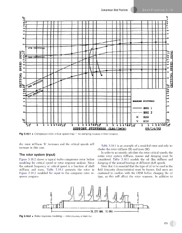
Fig 3.18.1 Compressor rotor critical speed map e no damping (Courtesy of Elliott Company)
the rotor stiffness ‘K’ increases and the critical speeds will Table 3.18.1 is an example of a modeled rotor and only in-
increase in this case.
cludes the rotor stiffness (K) and mass (M).
In order to accurately calculate the rotor critical speeds, the
The rotor system (input) entire rotor system stiffness, masses and damping must be
Figure 3.18.2 shows a typical turbo-compressor rotor before considered. Table 3.18.1 models the oil film stiffness and
modeling for critical speed or rotor response analysis. Since damping of the journal bearings at different shaft speeds.
the natural frequency or critical speed is a function of shaft Note that it is essential that the type of oil to be used in the
stiffness and mass, Table 3.18.1 presents the rotor in field (viscosity characteristics) must be known. End users are
Figure 3.18.2 modeled for input to the computer rotor re- cautioned to confirm with the OEM before changing the oil
sponse program. type, as this will affect the rotor response. In addition to
Fig 3.18.2 Rotor response modeling e rotor (Courtesy of Elliott Co.)
171