
Page 198 - Subyek Teknik Mesin - Forsthoffers Best Practice Handbook for Rotating Machinery by William E Forsthoffer
P. 198
Be st Practice 3 .18 Compressor Best Practices
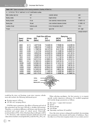
Table 3.18.1 Typical compressor oil film bearing parameters (Courtesy of Elliott Co.)
4 1.6"tilt 20.5" TB 3.0" shaft end 7.5e6.5" shaft Bendix coupling
Static bearing load (lbs) 897 diameter (inches) 4.00
Bearing station 12 length (inches) 1.60
Bearing location thrust diam assembly clearance (inches) 5.7487Ee03
Bearing type tilt pad diam machined clearance (inches) 8.7500Ee03
Location of load between pads inlet oil temperature (deg F) 120.0
Preload 0.343 type of oil DTEelight
(150SSU @100 F)
modeling the rotor and bearings, most rotor response calcula- When selecting machinery, the best practice is to request
tions also include the following additional inputs:
specific vendor experience references for installed equipment
- Bearing support stiffness with similar design parameters as follows:
- Oil film seal damping effects - Bear span O major shaft diameter
- Speeds
Of all the input parameters, the effects of bearing and seal oil
film parameters are the most difficult to calculate and measure. - Bearing design
- Seal design
Therefore, a correlation difference will always exist between the
predicted and actual values of critical speed. Historically, - Operating conditions (if possible)
predictedvaluesofNC 1 (firstcriticalspeed)generallyagreewithin Once the rotor system is adequately modeled, the remaining
5%. However, wide variations between predicted and actual input parameter is the amount and location of unbalance. Since
values above the first critical speed (NC 1 ) exist for NC 2 ,NC 3 ,etc. the objective of the rotor response study is to accurately predict
172