
Page 203 - Subyek Teknik Mesin - Forsthoffers Best Practice Handbook for Rotating Machinery by William E Forsthoffer
P. 203
Compressor Best Practices Best Practice 3 .19
DT for all hydrodynamic bearings. Also given in this figure is
the data necessary to calculate bearing pressure at the load
point.
As an exercise calculate the following for this bearing:
- Projected Area
A PROJECTED ¼ 5" 2"
¼ 10 square inches
- Pressure
¼ 3479 lb force O 10 square inches
¼ 347.9 psi on the oil film at load point
Condition monitoring
In order to determine the condition of any journal bearing, all
the parameters that determine its condition must be monitored.
Fig 3.19.3 Tilting pad journal bearing assembly (Courtesy of Figure 3.19.5 presents the eight parameters that determine
Kingsbury, Inc.) the condition of a hydrodynamic journal bearing along with
typical limits. You are advised to consult the manufacturer’s
instruction book for vendor recommended limits.
The most common hydrodynamic bearing for higher speed
One important parameter noted in Figure 3.19.5 that is fre-
applications is the tilt pad journal bearing shown in quently overlooked is shaft position. Change of shaft position
Figure 3.19.3. A tilting pad bearing offers the advantage of in-
creased contact area, since the individual pads conform to can only occur if the forces acting on a bearing change or if the
bearing surface wears. Figure 3.19.6 shows how shaft position is
the shaft orbit. In addition, this type is also a highly effective
anti-whirl bearing since the spaces between the pads prevent oil determined using standard shaft proximity probes.
Regardless of the parameters that are condition monitored,
whirl. Most end users specify tilt pad radial and thrust bearings
for turbo-compressor applications. relative change of condition determines if and when action is
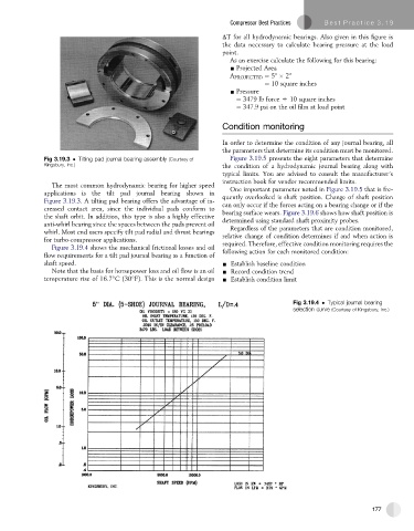
Figure 3.19.4 shows the mechanical frictional losses and oil required. Therefore, effective condition monitoring requires the
flow requirements for a tilt pad journal bearing as a function of following action for each monitored condition:
shaft speed. - Establish baseline condition
Note that the basis for horsepower loss and oil flow is an oil - Record condition trend
temperature rise of 16.7 C(30 F). This is the normal design - Establish condition limit
Fig 3.19.4 Typical journal bearing
selection curve (Courtesy of Kingsbury, Inc.)
177