
Page 204 - Subyek Teknik Mesin - Forsthoffers Best Practice Handbook for Rotating Machinery by William E Forsthoffer
P. 204
Be st Practice 3 .19 Compressor Best Practices
Parameter Limits
1. Radial vibration (peak to peak) 2.5 mils (60 microns)
2. Bearing pad temperature 220°F (108°C)
3. Radial shaft position (except for > 30° change and/or 30%
gearboxes where greater values are position change
normal from unloaded to loaded
operation)
4. Lube oil supply temperature 140°F (60°C)
5. Lube oil drain temperature 190°F (90°C)
6. Lube oil viscosity Off spec 50%
7. Lube oil flash point Below 200°F (100°C)
8. Lube oil particle size Greater than 25 microns
Condition monitoring parameters and their alarm limits according
to component:
1. Journal bearing (hydrodynamic)
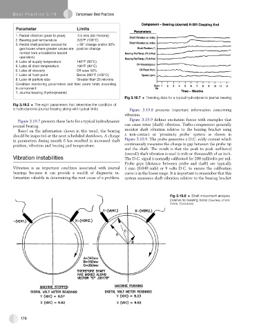
Fig 3.19.7 Trending data for a typical hydrodynamic journal bearing
Fig 3.19.5 The eight parameters that determine the condition of
a hydrodynamic journal bearing along with typical limits Figure 3.19.8 presents important information concerning
vibration.
Figure 3.19.7 presents these facts for a typical hydrodynamic Figure 3.19.9 defines excitation forces with examples that
journal bearing. can cause rotor (shaft) vibration. Turbo-compressors generally
Based on the information shown in this trend, the bearing monitor shaft vibration relative to the bearing bracket using
should be inspected at the next scheduled shutdown. A change a non-contact or ‘proximity probe’ system as shown in
in parameters during month 6 has resulted in increased shaft Figure 3.19.9. The probe generates a D.C. eddy current which
continuously measures the change in gap between the probe tip
position, vibration and bearing pad temperature.
and the shaft. The result is that the peak to peak unfiltered
(overall) shaft vibration is read in mils or thousandth of an inch.
Vibration instabilities The D.C. signal is normally calibrated for 200 millivolts per mil.
Probe gaps (distance between probe and shaft) are typically
Vibration is an important condition associated with journal 1 mm (0.040 mils) or 8 volts D.C. to ensure the calibration
bearings because it can provide a wealth of diagnostic in- curve is in the linear range. It is important to remember that this
formation valuable in determining the root cause of a problem. system measures shaft vibration relative to the bearing bracket
Fig 3.19.6 Shaft movement analysis
(relative to bearing bore) (Courtesy of M.E.
Crane, Consultant)
178