
Page 208 - Subyek Teknik Mesin - Forsthoffers Best Practice Handbook for Rotating Machinery by William E Forsthoffer
P. 208
Be st Practice 3 .20 Compressor Best Practices
Best
Best
Best Practice 3.20Practice 3.20Practice 3.20
Always check thrust pad temperature before changing from the equipment vendor, and use a hydraulic jack to load the thrust
axial displacement alarm and trip settings, to confirm that bearing assembly to operating values when the thrust clearance is
there is no excessive force being exerted on the thrust being set.
bearing assembly.
Hydrodynamic thrust bearings are typically monitored by dual axial Lessons Learned
shaft displacement probes and thrust pad resistance temperature The majority of plants that we visit have shutdown on axial
detectors in two pads on each side of the thrust collar. displacement when the shutdowns could have been
To ensure that axial displacement movement is real, always confirm avoided by checking bearing pad temperatures and in-
that thrust bearing pad temperatures are greater than 108 C (225 F). If creasing alarm and trip settings if this is below 108 C.
the thrust pad temperature is less than 108 C (225 F), the axial dis-
placement movement is the result of thrust assembly or bearing Benchmarks
bracket movements.
I have used this best practice since the 1990s when my article ‘Which
If thrust bearing assembly movements are confirmed, i.e. thrust way is it going?’ appeared in the Bently Nevada Orbit Magazine. This
bearing pad temperatures are less than 108 C (225 F), thrust bearing best practice has saved many plant shutdowns on axial displacement
alarms and trip temperatures can be increased to prevent unnecessary trips. These unnecessary shutdowns can significantly affect product
trips. revenue and quickly reduce machine reliability values.
If it is known that movement of the thrust bearing assembly com-
ponents is causing alarms and trips, obtain the operating thrust value
B.P. 3.20. Supporting Material
In every rotating machine utilizing reaction type blading, a sig-
nificant thrust is developed across the rotor by the action of the
impellers or blades. Also in the case of equipment incorporating
higher than atmospheric suction pressure, a thrust force is
exerted in the axial direction as a result of the pressure differ-
ential between the pressure in the case and atmospheric pressure.
In this section we will cover a specific rotor thrust example,
and calculate thrust balance for a specific case. We will see the
necessity of employing an axial force balance device, known as
a balance drum, in some applications. In many instances, the
absence of this device will result in excessive axial (thrust)
bearing loadings. For the case of a machine with a balance
device, the maintenance of the clearances on this device is of
utmost importance. In many older designs, the clearances are
maintained by a fixed, close-clearance bushing made out of
Babbitt, which has a melting temperature of approximately
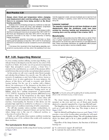
175 C (350 F), depending on the pressure differential across Fig 3.20.1 Double acting self-equalizing thrust bearing assembly
(thrust collar removed) (Courtesy of Elliott Company)
the balance drum. If the temperature in this region should
exceed this value, the effectiveness of the balance drum will
suddenly be lost and catastrophic failures can occur inside the The thrust bearing assembly consists of a thrust collar,
machine. Understanding the function of this device and the mounted on the rotor and two sets of thrust pads (usually
potential high axial forces involved in its absence is a very im- identical in capacity) supported by a base ring (Michell type).
portant aspect of condition monitoring of turbo-compressors. The Kingsbury type includes a set of leveling plates between
We will also examine various machine configurations, in- each set of pads and the base ring. This design is shown in
cluding natural balanced (opposed) thrust, and see how thrust Figure 3.20.2.
values change even in the case of a balanced machine, as Both the Michell and Kingsbury types are used. Figure 3.20.3
a function of machine flow rate. provides a view of the leveling plates providing the self-equal-
Finally, we will examine thrust system condition monitoring izing feature in the Kingsbury design. The self-equalizing feature
and discuss some of the confusion that results with monitoring allows the thrust pads to lie in a plane parallel to the thrust
these machines. collar.
Regardless of the design features, the functions of all thrust
The hydrodynamic thrust bearing bearings are:
A typical hydrodynamic double acting thrust bearing is pictured - To continuously support all axial loads
in Figure 3.20.1. - To maintain the axial position of the rotor
182