
Page 210 - Subyek Teknik Mesin - Forsthoffers Best Practice Handbook for Rotating Machinery by William E Forsthoffer
P. 210
Be st Practice 3 .20 Compressor Best Practices
Fig 3.20.5 Thrust bearing rated load vs. speed (Courtesy of Kingsbury Corp.)
Impeller thrust forces
Every reaction type compressor blade set or impeller produces
an axial force towards the suction of the blade or impeller. Refer
to Figure 3.20.7.
In this example, the net force towards the compressor suc-
tion is 8,900 N (2,000 lbs) for the set of conditions noted. Note
that the pressure behind the impeller is essentially constant at
344.75 kPa (50 psi), but the pressure on the front side of im-
peller varies from 344.75 to 275.8 kPa (50 to 40 psi), because of
the pressure drop across the eye labyrinth. Every impeller in
a multistage compressor will produce a specific value of axial
force towards its suction at a specific flow rate, speed and gas
composition. A change in any or all of these parameters will
produce a corresponding change in impeller thrust.
Rotor thrust balance
Figure 3.20.8 shows how a balance drum or opposed impeller
design reduces thrust force. The total impeller force is the sum of
the forces from the individual impellers. If the suction side of the
impellers is opposed, as noted in Figure 3.20.8, the thrust force
will be significantly reduced and can approach zero. If the suction
side of all impellers are the same (in series), the total impeller
thrust force can be very high, and may exceed the thrust bearing
rating. If this is the case, a balance drum must be mounted on the
rotor as shown in Figure 3.20.8. The balance drum face area is
varied such that the opposing force generated by the balance
drum reduces the thrust bearing load to an acceptable value. The
opposing thrust force results from the differential between
compressor discharge pressure (P F ) and compressor suction
pressure (P 1 ) since the area behind the balance drum is usually
referenced to the suction of the compressor. This is accomplished
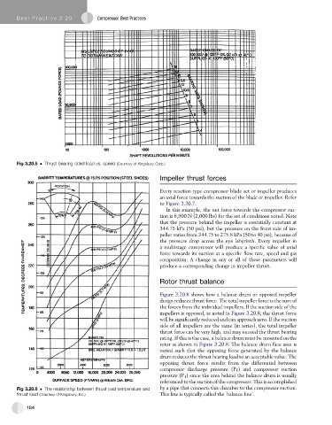
Fig 3.20.6 The relationship between thrust pad temperature and by a pipe that connects this chamber to the compressor suction.
‘
thrust load (Courtesy of Kingsbury, Inc.) This line is typically called the balance line’.
184