
Page 214 - Subyek Teknik Mesin - Forsthoffers Best Practice Handbook for Rotating Machinery by William E Forsthoffer
P. 214
Be st Practice 3 .22 Compressor Best Practices
Best Practice 3.22
Oil seals should be designed or modified to incorporate Lessons Learned
a flow through port if the difference between operating Compressor applications using oil seals in high suction
seal reference pressure and start-up pressure is greater pressure applications frequently have low seal MTBFs.
than 1,375 kPa (200 psi). RCFA investigations show that low pressure start-up con-
All compressor oil seals incorporate an atmospheric bushing. The ditions (nitrogen purge operation, etc.) with seals not using
atmospheric bushing flow is directly proportional to the seal reference a flow through design is the root cause of low MTBFs.
gas pressure since the seal system provides sealing oil at some con-
stant differential pressure above the reference pressure. Benchmarks
In many seal designs, the atmospheric bushing clearance provides
This best practice has been used since 1990, during the design phase
the only means of seal cooling and is designed to provide sufficient
to require flow-through type seal designs for high suction pressure
cooling oil flow for the rated operating reference gas pressure.
compressor applications where there is a difference of more than 1,375
If the reference pressure at start-up is less than 1,375 kPa (200 psid)
kPa (200 psi) between start-up and operating reference pressures.
than the operating reference pressure, insufficient atmospheric bush- Seal designs can be modified in the field to incorporate flow-
ing flow will be present during start-up, and bushing wear can result through designs, but require redesign of the seal oil system and seal
and cause a compressor trip on low differential seal oil pressure. housing modifications in the field.
Incorporating a flow through port into the seal design will allow
Use of flow through oil seals has resulted in seal MTBFs in excess of
sufficient cooling oil flow during low reference gas conditions that will 100 months, and compressor reliabilities in excess of 99.7%.
occur during start-up.
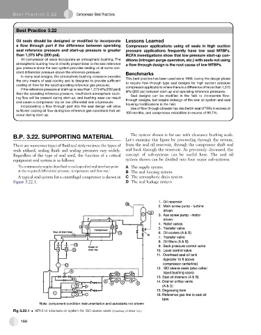
B.P. 3.22. SUPPORTING MATERIAL The system shown is for use with clearance bushing seals.
Let’sexamine this figure by proceeding through the system;
There are numerous types of fluid seal systems since the types of from the seal oil reservoir, through the compressor shaft seal
seals utilized, sealing fluids and sealing pressures vary widely. and back through the reservoir. As previously discussed, the
Regardless of the type of seal used, the function of a critical concept of sub-systems can be useful here. The seal oil
equipment seal system is as follows: system shown can be divided into four major sub-systems:
‘To continuously supply clean fluid to each specified seal interface point A The supply system
at the required differential pressure, temperature and flow rate’. B The seal housing system
A typical seal system for a centrifugal compressor is shown in C The atmospheric drain system
Figure 3.22.1. D The seal leakage system
Fig 3.22.1 API 614 lube/seal oil system for ISO-sleeve seals (Courtesy of Elliott Co.)
188