
Page 218 - Subyek Teknik Mesin - Forsthoffers Best Practice Handbook for Rotating Machinery by William E Forsthoffer
P. 218
Be st Practice 3 .22 Compressor Best Practices
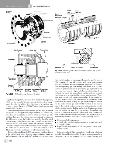
Fig 3.22.6 Bushing seal e top: oil film seal: bottom: seal oil flow
(Courtesy of Dresser-Rand)
this results in leakage of gas outward through the seal. It must be
fully understood that all bushing seals must continuously
maintain this liquid interface to ensure proper sealing. All sys-
tems incorporating gas side bushing seals must have the seal
system in operation whenever pressurized gas is present inside
the compressor case. If a liquid interface is not maintained, gas
will migrate across the atmospheric bushing seal and proceed
Fig 3.22.5 ISO carbon seal (Courtesy of Elliott Co.)
through the system returning back to the supply system. There
have been cases in such system designs where failure to operate
a significant change to the dynamic characteristics of equipment, the seal system when the compressor is pressurized have
which has the potential to cause damage to the critical equip- resulted in effectively turning the gas side bushing into a filter
ment. In order to achieve the objectives of a bushing seal, for the entire process gas system! This resulted in the supply
clearances are on the order of 0.0005" diametrical clearance per side of the seal oil system being filled with extensive debris,
inch of shaft diameter. which required lengthy flushing and system cleaning operations
Liquid bushing seals are also used for gas side seals, but their prior to putting the unit back into service. Remember, any
leakage rate will be significantly larger than that of a contact seal, system incorporating a gas side bushing seal must be designed
since they are essentially an orifice. When used as a gas side such that the entrance of process gas into the supply system is
bushing, therefore, the system must be designed to minimize prohibited at all time. This can be accomplished by either:
the differential across the bushing. As a result, the differential - Continuous buffer gas supply
control system utilized must be accurate enough to maintain the - A check valve installed as close as possible to seals in the seal
specified oil/gas differential under all operating conditions. oil supply header
The typical design differential across a gas side bushing seal is on - Rapid venting and isolation of the compressor case on seal
the order of five to ten psid. The accurate control of this system failure
differential is usually maintained by a level control system.
Referring back to Figure 3.22.6, one can see that functioning In the second and third cases above, supply seal oil piping
of the bushing seal totally depends on maintaining a liquid in- must be thoroughly checked for debris prior to re-start of the
terface between the seal and shaft surface. Failure to achieve compressor. It is our experience that many bushing seal
192