
Page 221 - Subyek Teknik Mesin - Forsthoffers Best Practice Handbook for Rotating Machinery by William E Forsthoffer
P. 221
Compressor Best Practices Best Practice 3 .22
Example 2: Contact type gas side seal e bushing
type atmospheric seal with orificed through flow
The only difference between this type of system and the pre-
vious system is that the back pressure is maintained constant by
a permanently installed through flow orifice. As a result, the
differential pressure control valve is installed on the inlet side of
the system. The process gas reference is still the same as before,
that is, to the highest pressure side of the compressor.
Figure 3.22.10 shows this type of system.
Let us examine the previous example case for this system and
observe the differences.
1. Gas Side Seal Flow ¼ 0
2. Atmospheric Side Seal Flow
Reference Pressure ¼ 0
Seal Flow ¼ 19.25 liters/min (5 GPM)
Reference Pressure ¼ 1,380 kPa (200 PSIG)
Seal Flow ¼ 46 liters/min (12 GPM)
3. Flow Through Flow (Orifice)
Minimum ¼ 2 liters/min (0.5 GPM)
Maximum ¼ 11.5 liters/min (3 GPM)
As can be seen, this system is more susceptible to high tem-
perature atmospheric bushing conditions at low suction pres-
sures, and must be observed during such operation to ensure
integrity of the atmospheric bushing. In this system, the control
valve will sense supply oil pressure to the seal chamber and
control a constant set differential, approximately 241 kPad (35
psid), between the reference gas pressure and the supply pres-
sure. If continued low pressure operation is anticipated with
such a system, consideration should be given to a means of
changing the minimum flow and maximum flow orifice for var-
ious operation points. Externally piped bypass orifices could be
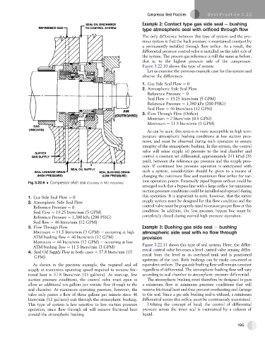
Fig 3.22.9 Compressor shaft seal (Courtesy of IMO Industries)
arranged such that a bypass line with a large orifice for minimum
suction pressure conditions could be installed and opened during
1. Gas Side Seal Flow ¼ 0 this operation. It is important to note, however, that the entire
2. Atmospheric Side Seal Flow supply system must be designed for this flow condition and the
Reference Pressure ¼ 0 control valve must be properly sized to ensure proper flow at this
condition. In addition, the low pressure bypass line must be
Seal Flow ¼ 19.25 liters/min (5 GPM)
Reference Pressure ¼ 1,380 kPa (200 PSIG) completely closed during normal high pressure operation.
Seal flow ¼ 46 liters/min (12 GPM)
3. Flow Through Flow Example 3: Bushing gas side seal e bushing
Minimum ¼ 11.5 liters/min (3 GPM) e occurring at high atmospheric side seal with no flow through
ATM bushing flow ¼ 46 liters/min (12 GPM) provision
Maximum ¼ 46 liters/min (12 GPM) e occurring at low
ATM bushing flow ¼ 11.5 liters/min (3 GPM) Figure 3.22.11 shows this type of seal system. Here, the differ-
4. Seal Oil Supply Flow in both cases ¼ 57.8 liters/min (15 ential control valve becomes a level control valve sensing differ-
ential from the level in an overhead tank and is positioned
GPM)
upstream of the unit. Both bushings can be easily conceived as
As shown in the previous example, the required seal oil equivalent orifices. The gas side bushing flow will remain constant
supply at maximum operating speed required to remove fric- regardless of differential. The atmospheric bushing flow will vary
tional heat is 57.8 liters/min (15 gal/min). At start-up, low according to seal chamber to atmospheric pressure differential.
suction pressure conditions, the control valve must open to The atmospheric bushing must therefore be designed to pass
allow an additional ten gallons per minute flow through to the a minimum flow at minimum pressure conditions that will
seal chamber. At maximum operating pressure, however, the remove frictional heat and thus prevent overheating and damage
valve only passes a flow of three gallons per minute since 46 to the seal. Since a gas side bushing seal is utilized, a minimum
liters/min (12 gal/min) exit through the atmospheric bushing. differential across this orifice must be continuously maintained.
This type of system is less sensitive to low suction pressure Utilizing the concept of head, the control of differential
operation, since flow through oil will remove frictional heat pressure across the inner seal is maintained by a column of
around the atmospheric bushing. liquid.
195