
Page 217 - Subyek Teknik Mesin - Forsthoffers Best Practice Handbook for Rotating Machinery by William E Forsthoffer
P. 217
Compressor Best Practices Best Practice 3 .22
Fig 3.22.3 Typical pump single
mechanical seal
to prevent emission of toxic vapors. The following is a discussion The seal employed is essentially a contact seal with some type of
of major types of seal combinations used in centrifugal com- lifting device to maintain a fixed minimum clearance between
pressor seal applications. the rotating faces. It is essential that the gas between these
surfaces be clean since any debris will quickly clog areas and
reduce the effectiveness of the lifting devices, consequently
Gas seals
resulting in rapid damage to the seal faces.
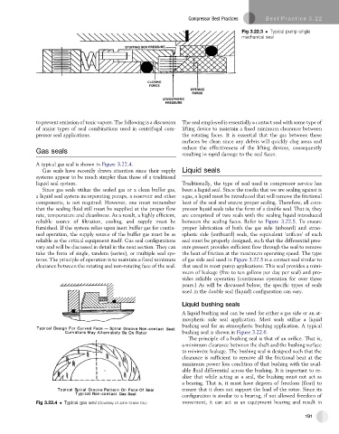
A typical gas seal is shown in Figure 3.22.4.
Gas seals have recently drawn attention since their supply Liquid seals
systems appear to be much simpler than those of a traditional
liquid seal system. Traditionally, the type of seal used in compressor service has
Since gas seals utilize the sealed gas or a clean buffer gas, been a liquid seal. Since the media that we are sealing against is
a liquid seal system incorporating pumps, a reservoir and other a gas, a liquid must be introduced that will remove the frictional
components, is not required. However, one must remember heat of the seal and ensure proper sealing. Therefore, all com-
that the sealing fluid still must be supplied at the proper flow pressor liquid seals take the form of a double seal. That is, they
rate, temperature and cleanliness. As a result, a highly efficient, are comprised of two seals with the sealing liquid introduced
reliable source of filtration, cooling, and supply must be between the sealing faces. Refer to Figure 3.22.5. To ensure
furnished. If the system relies upon inert buffer gas for contin- proper lubrication of both the gas side (inboard) and atmo-
ued operation, the supply source of the buffer gas must be as spheric side (outboard) seals, the equivalent ‘orifices’ of each
reliable as the critical equipment itself. Gas seal configurations seal must be properly designed, such that the differential pres-
vary and will be discussed in detail in the next section. They can sure present provides sufficient flow through the seal to remove
take the form of single, tandem (series), or multiple seal sys- the heat of friction at the maximum operating speed. The type
tems. The principle of operation is to maintain a fixed minimum of gas side seal used in Figure 3.22.5 is a contact seal similar to
clearance between the rotating and non-rotating face of the seal. that used in most pump applications. This seal provides a mini-
mum of leakage (five to ten gallons per day per seal) and pro-
vides reliable operation (continuous operation for over three
years.) As will be discussed below, the specific types of seals
used in the double seal (liquid) configuration can vary.
Liquid bushing seals
A liquid bushing seal can be used for either a gas side or an at-
mospheric side seal application. Most seals utilize a liquid
bushing seal for an atmospheric bushing application. A typical
bushing seal is shown in Figure 3.22.6.
The principle of a bushing seal is that of an orifice. That is,
a minimum clearance between the shaft and the bushing surface
to minimize leakage. The bushing seal is designed such that the
clearance is sufficient to remove all the frictional heat at the
maximum power loss condition of that bushing with the avail-
able fluid differential across the bushing. It is important to re-
alize that while acting as a seal, the bushing must not act as
a bearing. That is, it must have degrees of freedom (float) to
ensure that it does not support the load of the rotor. Since its
configuration is similar to a bearing, if not allowed freedom of
Fig 3.22.4 Typical gas seal (Courtesy of John Crane Co.) movement, it can act as an equipment bearing and result in
191