
Page 212 - Subyek Teknik Mesin - Forsthoffers Best Practice Handbook for Rotating Machinery by William E Forsthoffer
P. 212
Be st Practice 3 .20 Compressor Best Practices
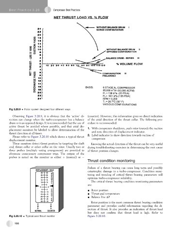
Fig 3.20.9 Rotor system designed four different ways
Observing Figure 3.20.8, it is obvious that the ‘active’ di- (counter). However, this information gives no direct indication
rection can change when the turbo-compressor has a balance of the axial direction of the thrust collar. The following pro-
drum or is an opposed design. It is recommended that the use of cedure is recommended:
active thrust be avoided where possible, and that axial dis-
placement monitors be labeled to allow determination of the 1. With compressor shutdown, push rotor towards the suction
thrust direction at all times. and note direction of displacement indicator.
2. Label indicator to show direction towards suction of
Please refer to Figure 3.20.10 which shows a typical thrust
displacement monitor. compressor.
These monitors detect thrust position by targeting the shaft Knowing the actual direction of the thrust can be very useful
end, thrust collar or other collar on the rotor. Usually two or during troubleshooting exercises in determining the root cause
three probes (multiple voting arrangement) are provided to of thrust position changes.
eliminate unnecessary compressor trips. The output of the
probes is noted on the monitor as either þ (normal) or
Thrust condition monitoring
Failure of a thrust bearing can cause long term and possibly
catastrophic damage to a turbo-compressor. Condition moni-
toring and trending of critical thrust bearing parameters will
optimize turbo-compressor reliability.
The critical thrust bearing condition monitoring parameters
are:
- Rotor position
- Thrust pad temperature
- Balance line DP
Rotor position is the most common thrust bearing condition
parameter and provides useful information regarding the di-
rection of thrust. It also provides an indication of thrust load
but does not confirm that thrust load is high. Refer to
Fig 3.20.10 Typical axial thrust monitor Figure 3.20.10.
186