
Page 213 - Subyek Teknik Mesin - Forsthoffers Best Practice Handbook for Rotating Machinery by William E Forsthoffer
P. 213
Compressor Best Practices Best Practice 3 .21
I personally recommend the first method since an active di-
rection of thrust does not have to be assumed.
As noted, axial displacement monitors only indicate the
quantity of thrust load. False indication of alarm or even trip
settings can come from:
- Compression of thrust bearing components
- Thermal expansion of probe adaptors or bearing brackets
- Loose probes
It is strongly recommended that any alarm or trip displace-
ment value be confirmed by thrust pad temperature if possible
prior to taking action. Please refer back to Figure 3.20.6 and
note that the thrust pad temperature in the case of thrust pad
overload is approximately 121 C (250 F). If an axial displace-
ment alarm or trip signal is activated, observe the corresponding
thrust pad temperature. If it is below 104 C (220 F), take the
following action:
- Observe thrust pads. If no evidence of high load is observed
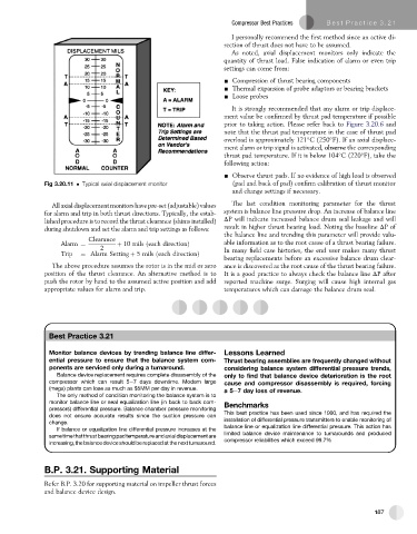
Fig 3.20.11 Typical axial displacement monitor (pad and back of pad) confirm calibration of thrust monitor
and change settings if necessary.
Allaxialdisplacementmonitorshavepre-set(adjustable)values The last condition monitoring parameter for the thrust
for alarm and trip in both thrust directions. Typically, the estab- system is balance line pressure drop. An increase of balance line
lished procedure is to record the thrust clearance (shims installed) DP will indicate increased balance drum seal leakage and will
during shutdown and set the alarm and trip settings as follows: result in higher thrust bearing load. Noting the baseline DPof
the balance line and trending this parameter will provide valu-
Clearance
Alarm ¼ þ 10 mils ðeach directionÞ able information as to the root cause of a thrust bearing failure.
2 In many field case histories, the end user makes many thrust
Trip ¼ Alarm Setting þ 5 mils ðeach directionÞ
bearing replacements before an excessive balance drum clear-
The above procedure assumes the rotor is in the mid or zero ance is discovered as the root cause of the thrust bearing failure.
position of the thrust clearance. An alternative method is to It is a good practice to always check the balance line DP after
push the rotor by hand to the assumed active position and add reported machine surge. Surging will cause high internal gas
appropriate values for alarm and trip. temperatures which can damage the balance drum seal.
Best Practice 3.21
Monitor balance devices by trending balance line differ- Lessons Learned
ential pressure to ensure that the balance system com- Thrust bearing assemblies are frequently changed without
ponents are serviced only during a turnaround. considering balance system differential pressure trends,
Balance device replacement requires complete disassembly of the only to find that balance device deterioration is the root
compressor which can result 5e7 days downtime. Modern large cause and compressor disassembly is required, forcing
(mega) plants can lose as much as $5MM per day in revenue. a5e7 day loss of revenue.
The only method of condition monitoring the balance system is to
monitor balance line or seal equalization line (in back to back com- Benchmarks
pressors) differential pressure. Balance chamber pressure monitoring
does not ensure accurate results since the suction pressure can This best practice has been used since 1990, and has required the
installation of differential pressure transmitters to enable monitoring of
change.
balance line or equalization line differential pressure. This action has
If balance or equalization line differential pressure increases at the
limited balance device maintenance to turnarounds and produced
sametimethatthrustbearingpadtemperatureandaxialdisplacementare
compressor reliabilities which exceed 99.7%
increasing, the balance device should be replaced at the next turnaround.
B.P. 3.21. Supporting Material
Refer B.P. 3.20 for supporting material on impeller thrust forces
and balance device design.
187