
Page 209 - Subyek Teknik Mesin - Forsthoffers Best Practice Handbook for Rotating Machinery by William E Forsthoffer
P. 209
Compressor Best Practices Best Practice 3 .20
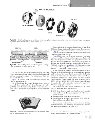
Fig 3.20.2 Small Kingsbury six-shoe, two direction thrust bearing. Left-hand group assembled, except for one shoe and ‘upper’ leveling plate.
Right-hand group disassembled (Courtesy of Kingsbury, Inc.)
Thrust pad temperature sensors, located directly behind the
Babbitt, at the pad maximum load point protect the compressor
by tripping the unit before steel-to-steel contact can occur.
Figure 3.20.5 presents different Kingsbury bearing size rated
capacities as a function of speed.
Figure 3.20.6 shows how thrust pad temperature and thrust
load are related for a given thrust bearing size and shaft speed.
Note that the greater the thrust load (psi), the smaller the oil
film and hence the greater the effect of oil viscosity on oil
flow and heat removal. Based on a maximum load of 3,448 kPa
Fig 3.20.3 Self-equalizing tilt-pad thrust bearing (view e looking (500 psi), it can be seen from Figure 3.20.6 that a turbo-com-
down on assembly) (Courtesy of Kingsbury, Inc.) pressor thrust bearing pad temperature trip setting should be
between 127 and 132 C (260 and 270 F).
As well as to support the rotor in an axial direction, the other
The first function is accomplished by designing the thrust function of the thrust bearing is to continuously maintain the
bearing to provide sufficient thrust area to absorb all thrust loads axial position of the rotor. This is accomplished by locating
without exceeding the support film (oil) pressure limit (ap- stainless steel shims between the thrust bearing assembly and
proximately 500 psi). compressor axial bearing support plates. The most common
Figure 3.20.4 shows what occurs when the support film thrust assembly clearance with the thrust shims installed is
pressure limit is exceeded. 0.275e0.35 mm (0.011e0.014"). These values vary with thrust
The oil film breaks down, thus allowing contact between bearing size. The vendor instruction book must be consulted to
the steel thrust collar and soft thrust bearing pad overlay determine the proper clearance.
(Babbitt). Once this thin layer (1/16") is worn away, steel to The following procedure is used to ensure that the rotor is
steel contact occurs resulting in significant turbo-compressor properly positioned in the axial direction.
damage.
1. With thrust shims removed, record total end float by pushing
rotor axially in both directions, typically 6.35e12.7 mm
(0.250e0.500").
2. Position rotor as stated in instruction book.
3. Install minimum number of stainless steel thrust shims to
limit end float to specified value. )
Proper running position of the rotor is critical to obtaining
optimum efficiency and preventing axial rubs during transient
and upset conditions (start-up, surge, etc.)
Fig 3.20.4 Evidence of overload on a tilt-pad self-equalizing thrust ) An excessive number of thrust shims act as a spring resulting in a greater than
bearing pad (Courtesy of Kingsbury, Inc.) specified axial clearance during full thrust load conditions.
183