
Page 223 - Subyek Teknik Mesin - Forsthoffers Best Practice Handbook for Rotating Machinery by William E Forsthoffer
P. 223
Compressor Best Practices Best Practice 3 .22
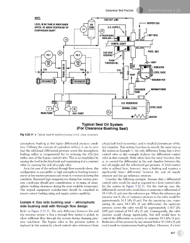
Fig 3.22.11 Typical seal oil system (Courtesy of M.E. Crane, Consultant)
atmospheric bushing at this higher differential pressure condi- a head tank level transmitter, and is installed downstream of the
tion. Utilizing the concept of equivalent orifices, it can be seen seal chamber. This system functions in exactly the same way as
that the additional differential pressure across the atmospheric the system in Example 1, the only difference being that a level
bushing orifice is compensated for by reducing the effective control valve in this example replaces the differential control
orifice area of the bypass control valve. This is accomplished by valve in that example. Both valves have the same function; that
sensing the level in the head tank and maintaining it at a constant is, to control the differential in the seal chamber between the
value by opening the seal oil supply valve. seal oil supply and the referenced gas pressure. A level control
As in the case of the orificed through flow example above, this valve is utilized here, however, since a bushing seal requires a
configuration is susceptible to high atmospheric bushing temper- significantly lower differential between the seal oil supply
atures at low suction pressures and must be monitored during this pressure and the gas reference pressure.
condition. Repeated high temperatures during low suction pres- Consider the following example. Assume that a differential
sure conditions should give consideration to re-sizing of atmo- control valve would be used as opposed to a level control valve
spheric bushing clearances during the next available turnaround. for the system in Figure 3.22.11. For the start-up case, the
The original equipment manufacturer should be consulted to differential control valve would have to maintain a differential of
ensure correct bushing sizing and supply system capability. 34.5 kPa (5 psi) over the reference gas. When the reference gas
pressure was 0, the oil upstream pressure to the valve would be
approximately 34.5 kPa (5 psi). For the operating case, main-
Example 4: Gas side bushing seal e atmospheric taining the same 34.5 kPa (5 psi) differential, the upstream
side bushing seal with through flow design
pressure across the valve would be approximately 1,413 kPa
Refer to Figure 3.22.11. The only difference between this and (205 psi) instead of 34.5 kPa (5 psi). Consequently, the valve
the previous system is that a through flow option is added, to position would change significantly, but still would have to
allow sufficient flow through the system during changing pres- control the differential accurately to maintain 34.5 kPa (5 psi).
sure conditions. The bypass valve in the previous system is Reduction of this pressure by any amount below 34.5 kPa (5 psi)
replaced in this system by a level control valve referenced from could result in instantaneous bushing failure. However, if a level
197