
Page 228 - Subyek Teknik Mesin - Forsthoffers Best Practice Handbook for Rotating Machinery by William E Forsthoffer
P. 228
Be st Practice 3 .23 Compressor Best Practices
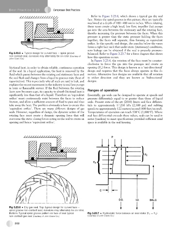
Refer to Figure 3.23.6, which shows a typical gas dry seal
face. Notice the spiral grooves in this picture; they are typically
machined at a depth of 100e400 micro inches. When rotating,
these vanes create a high head, low flow, impeller that pumps
gas into the area between the stationary and the rotating face,
thereby increasing the pressure between the faces. When this
pressure is greater than the static pressure holding the faces
together, the faces will separate, thus forming an equivalent
orifice. In this specific seal design, the annulus below the vanes
forms a tight face such that under static (stationary) conditions,
zero leakage can be obtained if the seal is properly pressure-
Fig 3.23.5 Typical design for curved face e spiral groove balanced. Refer to Figure 3.23.7 for a force diagram that shows
non-contact seal; curvature may alternately be on rotor (Courtesy of how this operation occurs.
John Crane Co.)
In Figure 3.23.6, therotation of thefacemustbecounter-
clockwise to force the gas into the passages and create an
frictional heat, in order to obtain reliable, continuous operation opening (F o ) force. This design is known as a ‘uni-directional’
of the seal. In a liquid application, the heat is removed by the design and requires that the faces always operate in this di-
fluid which passes between the rotating and stationary faces and rection. Alternative face designs are available that all rotation
the seal flush and changes from a liquid to gaseous state (heat of in either direction and they are known as ‘bidirectional’
vaporization). This is precisely why all seals are said to leak, and designs.
explains the recent movement in the industry to seal-less pumps
in toxic or flammable service. If the fluid between the rotating
faces now becomes a gas, its capacity to absorb frictional heat is Ranges of operation
significantly less than that of a liquid. Therefore an ‘equivalent Essentially, gas seals can be designed to operate at speeds and
orifice’ must continuously exist between the faces to reduce pressure differentials equal to or greater than those of liquid
friction, and allow a sufficient amount of fluid to pass and thus seals. Present state-of-the-art (2010) limits seal face differen-
take away the heat. The problem obviously is how to create this tials to approximately 17,250 kPa (2,500 psi) and rubbing
‘equivalent orifice’. There are many different designs of gas speeds to approximately 122 meters/second (400 feet/second).
seals. However, regardless of design, the dynamic action of the Temperatures of operation can reach 538 C (1,000 F). Where
rotating face must create a dynamic opening force that will seal face differential exceeds these values, seals can be used in
overcome the static closing forces acting on the seal to create an series (tandem) to meet specifications provided sufficient axial
opening and hence ‘equivalent orifice’. space is available in the seal housing.
Fig 3.23.6 Dry gas seal. Top: typical design for curved face e
spiral groove non-contact seal; curvature may alternately be on rotor;
Bottom: Typical spiral groove pattern on face of seal typical Fig 3.23.7 Hydrostatic force balance on seal stator (F C ¼ F O )
(Courtesy of John Crane Co.)
non-contact gas seal (Courtesy of John Crane Co.)
202