
Page 232 - Subyek Teknik Mesin - Forsthoffers Best Practice Handbook for Rotating Machinery by William E Forsthoffer
P. 232
Be st Practice 3 .23 Compressor Best Practices
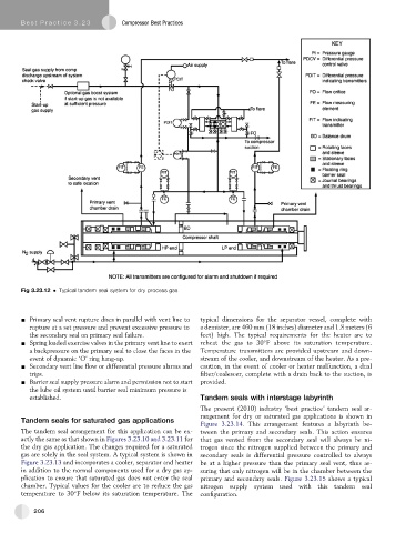
Fig 3.23.12 Typical tandem seal system for dry process gas
- Primary seal vent rupture discs in parallel with vent line to typical dimensions for the separator vessel, complete with
rupture at a set pressure and prevent excessive pressure to a demister, are 460 mm (18 inches) diameter and 1.8 meters (6
the secondary seal on primary seal failure. feet) high. The typical requirements for the heater are to
- Spring loaded exercise valves in the primary vent line to exert reheat the gas to 30 F above its saturation temperature.
a backpressure on the primary seal to close the faces in the Temperature transmitters are provided upstream and down-
event of dynamic ‘O’ ring hang-up. stream of the cooler, and downstream of the heater. As a pre-
- Secondary vent line flow or differential pressure alarms and caution, in the event of cooler or heater malfunction, a dual
trips. filter/coalescer, complete with a drain back to the suction, is
- Barrier seal supply pressure alarm and permission not to start provided.
the lube oil system until barrier seal minimum pressure is
established. Tandem seals with interstage labyrinth
The present (2010) industry ‘best practice’ tandem seal ar-
rangement for dry or saturated gas applications is shown in
Tandem seals for saturated gas applications
Figure 3.23.14. This arrangement features a labyrinth be-
The tandem seal arrangement for this application can be ex- tweenthe primaryand secondaryseals.Thisactionensures
actly the same as that shown in Figures 3.23.10 and 3.23.11 for that gas vented from the secondary seal will always be ni-
the dry gas application. The changes required for a saturated trogen since the nitrogen supplied between the primary and
gas are solely in the seal system. A typical system is shown in secondary seals is differential pressure controlled to always
Figure 3.23.13 and incorporates a cooler, separator and heater be at a higher pressure than the primary seal vent, thus as-
in addition to the normal components used for a dry gas ap- suring that only nitrogen will be in the chamber between the
plication to ensure that saturated gas does not enter the seal primary and secondary seals. Figure 3.23.15 shows a typical
chamber. Typical values for the cooler are to reduce the gas nitrogen supply system used with this tandem seal
temperature to 30 F below its saturation temperature. The configuration.
206