
Page 229 - Subyek Teknik Mesin - Forsthoffers Best Practice Handbook for Rotating Machinery by William E Forsthoffer
P. 229
Compressor Best Practices Best Practice 3 .23
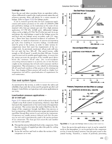
Leakage rates
Since the gas seal when operating forms an equivalent orifice,
whose differential is equal to the supply pressure minus the seal
reference pressure, there will always be a certain amount of
leakage. Refer to Figure 3.23.8 for leakage graphs.
It can be stated in general, that for most compressor appli-
cations with suction pressures on the order of 3,450 kPa (500
psi) and below, leakage can be maintained at the order of one
standard cubic foot per minute per seal. For a high pressure
application (17,750 kPa (2,500 psi)), differential leakage
3
values can be as high as 8.5 Nm /hr (5 scfm) per seal. As in any
seal design, the total leakage is equal to the leakage across the
seal faces and any leakage across secondary seals (‘O’ rings,
etc.). There have been reported incidences of explosive ‘O’
ring failure on rapid decompression of systems incorporating
gas seals, thus resulting in excessive leakage. Consideration
must be given to the system, in order to tailor system de-
compression times that meet the requirements of the sec-
ondary seals. As previously mentioned, all gas seals will leak,
but not until the face ‘lifts-off’. This speed known, oddly
enough, as ‘lift off speed’ is usually less than 500 rpm. Caution
must be exercised in variable speed applications, to ensure that
the system prevents the operation of the variable speed driver
below this minimum lift-off value. One recommendation
concerning instrumentation is to provide one or two thermo-
couples in the stationary face of each seal to measure seal face
temperature. This information is very valuable in determining
lift-off speed and condition of the grooves in the rotating seal
face. Any clogging of these grooves will result in a higher face
temperature and will be a good indication of requirement for
seal maintenance.
Gas seal system types
As mentioned in this section, in order to ensure the safety and
reliability of gas seals, the system must be properly specified and
designed. Listed below are typical gas seal system applications in
use today.
Low/medium pressure applications e
air or inert gas
Figure 3.23.2 shows such a system, which is identical to that of
a liquid pump flush system incorporating relatively clean fluid
that meets the requirements of the seal in terms of temperature
and pressure. This system takes the motive fluid from the dis-
charge of the compressor through dual filters (ten microns or
less) incorporating a differential pressure gauge and proportions
equal flow through flow meters to each seal on the compressor.
Compressors are usually pressure balanced such that the pres-
sure on each end is approximately equal to the suction pressure
of the compressor. The clean gas then enters the seal chamber
and has two main paths:
Fig 3.23.8 Dry gas seal leakage rates (Courtesy of John Crane Co.)
A. Through the internal labyrinth back to the compressor. Note
that the majority of supplied gas takes this path for cooling Since the gas in this application is inert, it can be vented di-
purposes (99%). rectly to the atmosphere, or can be put back to the compressor
B. Across the seal face and back to either the suction of the suction. It must be noted, however, that this port is next to the
compressor or to vent. journal bearing. Therefore, a means of positively preventing
203