
Page 227 - Subyek Teknik Mesin - Forsthoffers Best Practice Handbook for Rotating Machinery by William E Forsthoffer
P. 227
Compressor Best Practices Best Practice 3 .23
Considerations for system design exceed that of a liquid seal system, and the operating costs can
be reduced.
As mentioned above, there are disadvantages to a gas seal Before moving to the next section, however, one must
system; which are not insurmountable but must be considered consider that relative reliability of gas and liquid seal systems
in the design of such a system. These considerations are as are a function of proper specification, design, etc. as mentioned
follows: previously. A properly designed liquid seal system, which is
well operated and maintained, can achieve the reliabilities of
Sensitivity to dirt e since clearances between seal faces are a gas seal system. Also, when one considers the operating costs
usually less than 0.0005 inch and seal design is essential to of the two systems, various factors must be considered. While
proper operation, the fluid passing between the faces must be the loss of costly seal oil is eliminated, with a gas seal system
clean (5e10 microns maximum particle size). If it is not the (assuming oil ingestion from the lube system does not occur)
small grooves (indentations) necessary for seal force separation the loss of process gas, while minimal, can be expensive. It is
will become plugged thus causing face contact and seal failure. argued that the loss of process gas from a liquid seal system
Sensitivity to saturated gas e saturated fluids increase the through drainer vents and degassing tank vents is also signifi-
probability of groove (indentation) blockage. cant. While this may be true in many cases, a properly speci-
Lift-off speed e as will be explained below, a minimum speed fied, designed and operated liquid seal system can minimize
is required for operation. Care must be taken in variable speed process gas leakage such that it is equal or even less than that
operation to ensure that operation is always above this speed. It of a gas seal.
is recommended that the seal test be conducted for a period at There is no question that gas seal systems contain far fewer
turning gear speed to confirm proper ‘lift off’ followed by seal components and are easier to maintain than liquid seal systems.
face inspection. These systems will be used extensively in the years ahead. The
Positive prevention of toxic gas leaks to atmosphere e since all intention of this discussion is to point out that existing liquid seal
seals leak, the system must be designed to preclude the systems that cannot be justified for retrofit, or cannot be
possibility of toxic of flammable gas leaks out of the system. This retrofitted easily, can be modified to minimize outward gas
will be discussed in detail below. leakage and optimize safety and reliability.
Possible oil ingestion from the lube system e a suitable
separation seal must be provided to eliminate the possibility of
oil ingestion from the bearings. Whenever a gas seal system is Dry gas seal design
utilized, the design of the critical equipment by definition
incorporates a separate lube oil and seal system. Consideration Principles of operation
must be given during the design or retrofit phases to the
separation between the liquid (lube) and gas seal system. The intention of this sub-section is to present a brief detail of the
‘O’ ring (secondary seal components) design and principles of operation of a dry gas seal in a conceptual form. The
maintenance e most seal vendors state that ‘O’ ring life is reader is directed to any of the good literature available on this
subject for a detailed review of gas seal design.
limited and they should be changed every five years. This
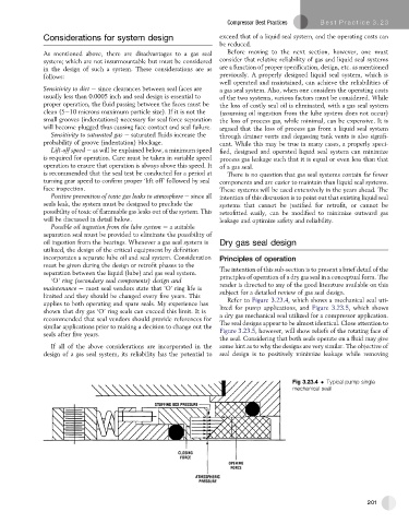
Refer to Figure 3.23.4, which shows a mechanical seal uti-
applies to both operating and spare seals. My experience has lized for pump applications, and Figure 3.23.5, which shows
shown that dry gas ‘O’ ring seals can exceed this limit. It is
recommended that seal vendors should provide references for a dry gas mechanical seal utilized for a compressor application.
similar applications prior to making a decision to change out the The seal designs appear to be almost identical. Close attention to
seals after five years. Figure 3.23.5, however, will show reliefs of the rotating face of
the seal. Considering that both seals operate on a fluid may give
If all of the above considerations are incorporated in the some hint as to why the designs are very similar. The objective of
design of a gas seal system, its reliability has the potential to seal design is to positively minimize leakage while removing
Fig 3.23.4 Typical pump single
mechanical seal
201