
Page 231 - Subyek Teknik Mesin - Forsthoffers Best Practice Handbook for Rotating Machinery by William E Forsthoffer
P. 231
Compressor Best Practices Best Practice 3 .23
Fig 3.23.10 Tandem seal (Courtesy of Flowserve Corp.)
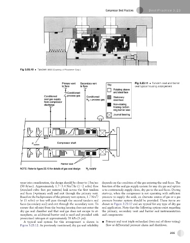
Fig 3.23.11 Tandem seal and barrier
seal typical housing arrangement
wear into consideration, the design should be closer to 15m/sec depends on the condition of the gas entering the seal faces. The
3
(50 ft/sec). Approximately 1.7e3.4 Nm /hr (1e2 scfm) flow function of the seal gas supply system for any dry gas seal option
(standard cubic feet per minute) leak across the first tandem is to continuously supply clean, dry gas to the seal faces. During
seal faces ()primary seal) and exit through the primary vent. start-up, when the compressor is not operating with sufficient
3
Based on the backpressure of the primary vent system, 1.7 Nm / pressure to supply the seals, an alternate source of gas or a gas
hr (1 scfm) or less will pass through the second tandem seal pressure booster system should be provided. These items are
faces (secondary seal) and exit through the secondary vent. To shown in Figure 3.23.12 and are typical for any type of dry gas
ensure that oil mist from the bearing housing does not enter the seal application. Note that the following options exist regarding
dry gas seal chamber and that seal gas does not escape to at- the primary, secondary vent and barrier seal instrumentation
mosphere, an additional barrier seal is used and provided with and components:
pressurized nitrogen at approximately 35 kPa (5 psi).
A typical seal system for this arrangement is shown in - Primary seal vent triple redundant (two-out-of-three voting)
Figure 3.23.12. As previously mentioned, dry gas seal reliability flow or differential pressure alarm and shutdown.
205