
Page 304 - Subyek Teknik Mesin - Forsthoffers Best Practice Handbook for Rotating Machinery by William E Forsthoffer
P. 304
Steam Turbine Best Practices Be st Practice 5.7
B.P. 5.7. Supporting Material design. And even if it is, the thrust is zero only at one set of
operating conditions.
Figure 5.7.2 shows a rotor system designed four different
Rotor thrust balance
ways. Note how the thrust always changes with the flow rate
regardless of the design. Another misconception regarding
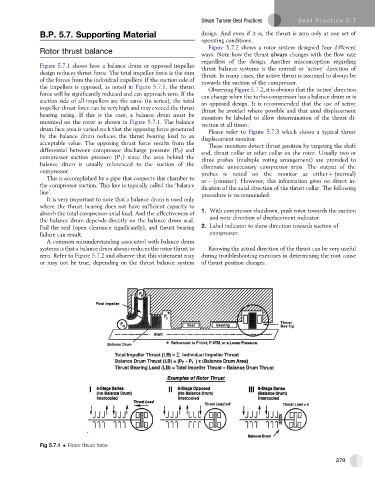
Figure 5.7.1 shows how a balance drum or opposed impeller thrust balance systems is the normal or ‘active’ direction of
design reduces thrust force. The total impeller force is the sum thrust. In many cases, the active thrust is assumed to always be
of the forces from the individual impellers. If the suction side of towards the suction of the compressor.
the impellers is opposed, as noted in Figure 5.7.1, the thrust Observing Figure 5.7.2, it is obvious that the ‘active’ direction
force will be significantly reduced and can approach zero. If the can change when the turbo-compressor has a balance drum or is
suction side of all impellers are the same (in series), the total an opposed design. It is recommended that the use of active
impeller thrust force can be very high and may exceed the thrust thrust be avoided where possible and that axial displacement
bearing rating. If this is the case, a balance drum must be
monitors be labeled to allow determination of the thrust di-
mounted on the rotor as shown in Figure 5.7.1. The balance rection at all times.
drum face area is varied such that the opposing force generated
Please refer to Figure 5.7.3 which shows a typical thrust
by the balance drum reduces the thrust bearing load to an displacement monitor.
acceptable value. The opposing thrust force results from the These monitors detect thrust position by targeting the shaft
differential between compressor discharge pressure (P F ) and end, thrust collar or other collar on the rotor. Usually two or
compressor suction pressure (P 1 ) since the area behind the three probes (multiple voting arrangement) are provided to
balance drum is usually referenced to the suction of the eliminate unnecessary compressor trips. The output of the
compressor. probes is noted on the monitor as either þ (normal)
This is accomplished by a pipe that connects this chamber to or (counter). However, this information gives no direct in-
the compressor suction. This line is typically called the ‘balance dication of the axial direction of the thrust collar. The following
line’. procedure is recommended:
It is very important to note that a balance drum is used only
where the thrust bearing does not have sufficient capacity to
1. With compressor shutdown, push rotor towards the suction
absorb the total compressor axial load. And the effectiveness of
the balance drum depends directly on the balance drum seal. and note direction of displacement indicator.
Fail the seal (open clearance significantly), and thrust bearing 2. Label indicator to show direction towards suction of
failure can result. compressor.
A common misunderstanding associated with balance drum
systems is that a balance drum always reduces the rotor thrust to Knowing the actual direction of the thrust can be very useful
zero. Refer to Figure 5.7.2 and observe that this statement may during troubleshooting exercises in determining the root cause
or may not be true, depending on the thrust balance system of thrust position changes.
Fig 5.7.1 Rotor thrust force
279