
Page 301 - Subyek Teknik Mesin - Forsthoffers Best Practice Handbook for Rotating Machinery by William E Forsthoffer
P. 301
Be st Practice 5 .6 Steam Turbine Best Practices
The maximum desired design wedge pressure for oil is ap-
proximately 3,450 kPa (500 psi). However, it has been common
practice to limit hydrodynamic bearing loads to approximately
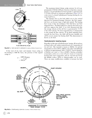
1,725 kPa (250 psi) in compressor applications. Figure 5.6.2 is
a side view of a simple hydrodynamic bearing showing the dy-
namic load forces.
The primary force is the load which acts in the vertical
direction for horizontal bearings. However, the fluid tangen-
tial force can become large at high shaft speeds. The bearing
load vector is then the resultant of the load force and fluid
tangential force. The fluid radial force opposes the load vector
and thus supports the shaft. It has been demonstrated that
the average velocity of the oil flow is approximately 47-52%
of the shaft velocity. The fluid tangential force is proportional
to the journal oil flow velocity. If the fluid tangential force
exceeds the load force, the shaft will become unstable and
will be moved around the bearing shell. This phenomenon is
known as oil whirl.
Hydrodynamic bearing types
Regardless of the type of hydrodynamic bearing, all its surfaces
are lined with a soft, surface material made of a composition of
tin and lead. This material is known as Babbitt. Its melting
Fig 5.6.1 Hydrodynamic Lubrication (Courtesy of Bently Nevada Corp.)
temperature is above 204 C (400 F), but under load will begin
If the total of the static and dynamic forces acting on to deform at approximately 160 C(320 F). Typical thickness
of Babbitt over steel is 1.5mm (0.060"). Bearing embedded
the bearing is 1600 lbs force, the pressure of the support
wedge is: temperatureprobesare amost effectivemeans of measuring
bearing load point temperature and are inserted just below
1600 Lb FORCE the Babbitt surface. RTDs or thermocouples can be used.
P ¼ 2
8in There are many modifications available to increase the load
¼ 200 psi
Fig 5.6.2 Shaft/bearing dynamics (Courtesy of Bently Nevada Corp.)
276