
Page 302 - Subyek Teknik Mesin - Forsthoffers Best Practice Handbook for Rotating Machinery by William E Forsthoffer
P. 302
Steam Turbine Best Practices Be st Practice 5.6
effectiveness of hydrodynamic bearings. Among the methods
available are:
- Copper backed Babbitt or ‘Trimetal’ e to aid in heat removal
- Back pad cooling e used on tilt pad bearings to remove heat
- Direct cooling e directing cool oil to maximum load points
A typical straight sleeve hydrodynamic journal bearing is
shown in Figure 5.6.3.
Straight sleeve bearings are used for low shaft speeds (less
than 5,000 rpm) or for older turbo-compressor designs. Fre-
quently, they are modified to incorporate a pressure dam, in the
direction of rotation. This pressure dam must be positioned in
the top half of the bearing to increase the load vector (see
Figure 5.6.2). This ensures that the tangential force vector will
be small relative to the load vector, thus preventing shaft in-
stability. It should be noted that incorrect assembly of the
pressure dam in the lower half of the bearing will render this
Fig 5.6.5 Tilting pad journal bearing assembly (Courtesy of Kingsbury,
Inc.)
type of bearing unstable. When shaft speed is high, other al-
ternatives to prevent rotor instabilities are noted in Figure 5.6.4.
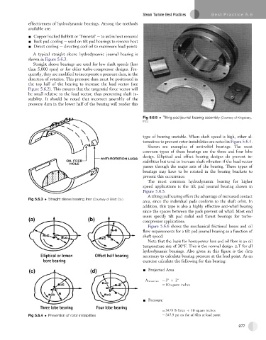
Shown are examples of anti-whirl bearings. The most
common types of these bearings are the three and four lobe
design. Elliptical and offset bearing designs do prevent in-
stabilities but tend to increase shaft vibration if the load vector
passes through the major axis of the bearing. These types of
bearings may have to be rotated in the bearing brackets to
prevent this occurrence.
The most common hydrodynamic bearing for higher
speed applications is the tilt pad journal bearing shown in
Figure 5.6.5.
A tilting pad bearing offers the advantage of increased contact
Fig 5.6.3 Straight sleeve bearing liner (Courtesy of Elliott Co.)
area, since the individual pads conform to the shaft orbit. In
addition, this type is also a highly effective anti-whirl bearing
since the spaces between the pads prevent oil whirl. Most end
users specify tilt pad radial and thrust bearings for turbo-
compressor applications.
Figure 5.6.6 shows the mechanical frictional losses and oil
flow requirements for a tilt pad journal bearing as a function of
shaft speed.
Note that the basis for horsepower loss and oil flow is an oil
temperature rise of 30 F. This is the normal design 6T for all
hydrodynamic bearings. Also given in this figure is the data
necessary to calculate bearing pressure at the load point. As an
exercise calculate the following for this bearing:
- Projected Area
¼ 5" 2"
A PROJECTED
¼ 10 square inches
- Pressure
¼ 3479 lb force O 10 square inches
Fig 5.6.4 Prevention of rotor instabilities ¼ 347.9 psi on the oil film at load point
277