
Page 296 - Subyek Teknik Mesin - Forsthoffers Best Practice Handbook for Rotating Machinery by William E Forsthoffer
P. 296
Steam Turbine Best Practices Be st Practice 5.5
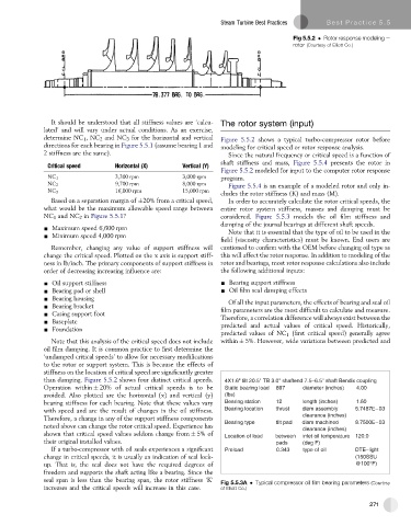
Fig 5.5.2 Rotor response modeling e
rotor (Courtesy of Elliott Co.)
It should be understood that all stiffness values are ‘calcu- The rotor system (input)
lated’ and will vary under actual conditions. As an exercise,
determine NC 1 ,NC 2 and NC 3 for the horizontal and vertical Figure 5.5.2 shows a typical turbo-compressor rotor before
directions for each bearing in Figure 5.5.1 (assume bearing 1 and modeling for critical speed or rotor response analysis.
2 stiffness are the same). Since the natural frequency or critical speed is a function of
Critical speed Horizontal (X) Vertical (Y) shaft stiffness and mass, Figure 5.5.4 presents the rotor in
Figure 5.5.2 modeled for input to the computer rotor response
NC 1 3,300 rpm 3,000 rpm program.
NC 2 9,700 rpm 8,000 rpm Figure 5.5.4 is an example of a modeled rotor and only in-
NC 3 16,000 rpm 15,000 rpm
cludes the rotor stiffness (K) and mass (M).
Based on a separation margin of 20% from a critical speed, In order to accurately calculate the rotor critical speeds, the
what would be the maximum allowable speed range between entire rotor system stiffness, masses and damping must be
NC 1 and NC 2 in Figure 5.5.1? considered. Figure 5.5.3 models the oil film stiffness and
damping of the journal bearings at different shaft speeds.
- Maximum speed 6,600 rpm
- Minimum speed 4,000 rpm Note that it is essential that the type of oil to be used in the
field (viscosity characteristics) must be known. End users are
Remember, changing any value of support stiffness will cautioned to confirm with the OEM before changing oil type as
change the critical speed. Plotted on the x axis is support stiff- this will affect the rotor response. In addition to modeling of the
ness in lb/inch. The primary components of support stiffness in rotor and bearings, most rotor response calculations also include
order of decreasing increasing influence are: the following additional inputs:
- Oil support stiffness - Bearing support stiffness
- Bearing pad or shell - Oil film seal damping effects
- Bearing housing Of all the input parameters, the effects of bearing and seal oil
- Bearing bracket
- Casing support foot film parameters are the most difficult to calculate and measure.
Therefore, a correlation difference will always exist between the
- Baseplate
- Foundation predicted and actual values of critical speed. Historically,
predicted values of NC 1 (first critical speed) generally agree
Note that this analysis of the critical speed does not include within 5%. However, wide variations between predicted and
oil film damping. It is common practice to first determine the
‘undamped critical speeds’ to allow for necessary modifications
to the rotor or support system. This is because the effects of
stiffness on the location of critical speed are significantly greater
than damping. Figure 5.5.2 shows four distinct critical speeds. 4X1.6" tilt 20.5" TB 3.0" shaftend 7.5–6.5" shaft Bendix coupling
Operation within 20% of actual critical speeds is to be Static bearing load 897 diameter (inches) 4.00
avoided. Also plotted are the horizontal (x) and vertical (y) (lbs)
bearing stiffness for each bearing. Note that these values vary Bearing station 12 length (inches) 1.60
with speed and are the result of changes in the oil stiffness. Bearing location thrust diam assembly 5.7487E 03
Therefore, a change in any of the support stiffness components clearance (inches)
noted above can change the rotor critical speed. Experience has Bearing type tilt pad diam machined 8.7500E 03
clearance (inches)
shown that critical speed values seldom change from 5% of Location of load between inlet oil temperature 120.0
their original installed values. pads (deg F)
If a turbo-compressor with oil seals experiences a significant Preload 0.343 type of oil DTE–light
change in critical speeds, it is usually an indication of seal lock- (150SSU
up. That is, the seal does not have the required degrees of @100°F)
freedom and supports the shaft acting like a bearing. Since the
seal span is less than the bearing span, the rotor stiffness ‘K’
Fig 5.5.3A Typical compressor oil film bearing parameters (Courtesy
increases and the critical speeds will increase in this case. of Elliott Co.)
271