
Page 292 - Subyek Teknik Mesin - Forsthoffers Best Practice Handbook for Rotating Machinery by William E Forsthoffer
P. 292
Steam Turbine Best Practices Be st Practice 5.4
Best
Best Practice 5.4Practice 5.4Practice 5.4
Best
Trend “after first stage” pressures vs. steam flow, as well operations and reliability personnel with immediate indication of
as phase angle to detect the onset of steam path fouling, in fouling.
order to determine the necessity for water washing.
Ensure that after first stage, pressures are trended and plotted on Lessons Learned
vendor-provided “after first stage” pressure vs. steam flow curves. Failure to observe, trend and use the vendor’s “after first
If after the first stage, the pressure falls above the curve for stage” pressure vs. steam flow curve will result in un-
a measured steam flow, the turbine is beginning to foul. expected turbine vibration that can trip the unit on high
Further confirmation is any change in vibration phase angles once vibration.
abnormal first stage pressures are observed.
Fouling will initially accumulate evenly on a rotor, but will break off
Consult management, and plan for a timely on-line turbine water
unevenly, so causing unbalanced vibration that can reach levels that
wash, closely following vendor recommendations.
are high enough to trip the turbine.
The above procedure also applies to the post-first stage pressure in
the low pressure section of extraction turbines. Benchmarks
If transmitters are installed, this information can be brought into
the control room DCS and plotted on the vendor curves to provide This best practice has been used since the 1990s, achieving steam tur-
bine reliabilities above 99.5% and to direct timely on-line water washes.
B.P. 5.4. Supporting Material foulant cause it to chip off with time as it becomes dry and
brittle. This results in a change in rotor balance and a change in
performance (head and efficiency).
The mechanism of fouling
As mentioned earlier, one can reduce any blade row or impeller The effect of fouling on the operating point
to a series of equivalent orifices. Flow is a function of area and
velocity. If we refer back to the previous example of a backward leaning
Whenever any blade row or impeller is designed, the designer centrifugal compressor impeller, the effect of fouling can be
sets the inlet and discharge blade areas such that optimum ve- understood. Figure 5.4.2 shows the effect of fouling on the
locities relative to the blade will be achieved at each location. By relative velocity.
a combination of tests and experience, designers have defined Since the area of the flow passage is reduced when the im-
optimum relative velocity rather well. Therefore the resulting peller is fouled, V REL will increase, the flow angle, f, will in-
inlet and discharge areas will produce optimum velocities and crease, and therefore result in an absolute velocity (increased R)
corresponding optimum impeller efficiencies. If, however, the as shown in Figure 5.4.3.
areas were to change, and flow passages were to become rough The increase in f and R due to fouling will reduce the tan-
and non-continuous, the performance of the impeller would gential velocity of the gas as shown in Figure 5.4.4.
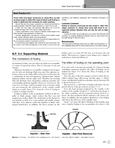
change as a result. Figure 5.4.1 shows the effect of fouling on Since the head (energy) produced by the impeller is the
a closed centrifugal impeller. product of the impeller tip speed ‘U’, which does not change in
Fouling is defined as the accumulation of debris in the im- the fouled condition, and the tangential velocity which is re-
peller or blade passage, which reduces the flow area and duced, the head produced will be reduced in the fouled con-
roughens the surface finish. The distribution of the foulant on dition. In addition, the non-uniform distribution of the foulant
the impeller or blade row is non-uniform and usually changes will reduce the efficiency of the impeller stage.
with time. Flow patterns within the impeller or blade cause Figure 5.4.5 shows the effect of fouling on the impeller stage
unequal distribution. In addition, the forces exerted on the curve. Impeller fouling is the accumulation of material in the
Fig 5.4.1 Fouling e the effect on the operating point. Left: impeller e side view. Right: impeller e side plate removed
267