
Page 295 - Subyek Teknik Mesin - Forsthoffers Best Practice Handbook for Rotating Machinery by William E Forsthoffer
P. 295
Be st Practice 5 .5 Steam Turbine Best Practices
r ffiffiffiffiffi
In the early days of rotor design, it was thought that the rotor K
system consisted primarily of the rotor supported by the bear- F NATURAL ¼ M
ings. This led to the assumption that only the stiffness of the
Where: K ¼ Stiffness
rotor supported by rigid bearings needed to be considered in the
analysis of the natural frequency. Countless machinery prob- M ¼ Mass
lems have proven this assumption to be false over the years. The When excited by an external force, any object will vibrate at
concept of the ‘rotor system’ must be thoroughly understood. its natural frequency. If the frequency of the exciting force is
The rotor system consists of the rotor itself, the characteristics equal to the natural frequency of the object, and no damping is
of the oil film that support the rotor, the bearing, the bearing present, the object can vibrate to destruction. Therefore, if the
housing, the compressor case that supports the bearing, com- frequency of an exciting force equals the natural frequency of an
pressor support (base plate), and the foundation. The stiffness object, the exciting force is operating at the ‘critical frequency’.
and damping characteristics of all of these components together Rotor speed is one of the most common external forces in
result in the total rotor system that produces the rotor response turbo-machinery. When the rotor operates at any rotor system
to excitation forces. natural frequency, it is said that the rotor is operating at its
We will examine a typical rotor response case in this section critical speed. The critical speed of a rotor is commonly desig-
and note the various assumptions, the procedure modeling, the nated as NC and the corresponding natural frequencies or
placement of unbalance, and the response calculation output, and critical speeds are: NC 1 ,NC 2 ,NC 3 , etc.
discuss the correlation of these calculations to actual test results. Every turbo-compressor must have its rotor system critical
speeds determined prior to manufacture. In this section, we will
follow the procedure for the determination of the necessary pa-
Critical speeds rameters to define a rotor system’s critical speed. The procedure is
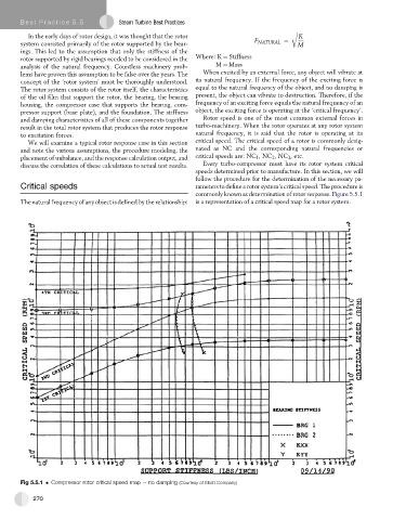
commonly known as determination of rotor response. Figure 5.5.1
The natural frequency of any object is defined by the relationship: is a representation of a critical speed map for a rotor system.
Fig 5.5.1 Compressor rotor critical speed map e no damping (Courtesy of Elliott Company)
270