
Page 294 - Subyek Teknik Mesin - Forsthoffers Best Practice Handbook for Rotating Machinery by William E Forsthoffer
P. 294
Steam Turbine Best Practices Be st Practice 5.5
The causes of fouling in steam turbines
The causes of fouling are described in Figure 5.4.6.
Boiler upsets resulting in deposits of calcium and/or silica on
turbine blades
Improper boiler feed water treatment resulting in calcium and/or
silica deposits on turbine blades
Fig 5.4.6 The causes of fouling in steam turbines
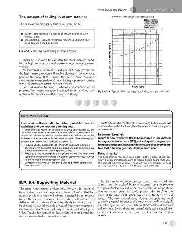
Figure 5.4.7 shows a typical “after first stage” pressure curve
for the high pressure section of an extraction/condensing steam
turbine.
Measurement of steam flow and post-first stage pressure in
the high pressure section will enable plotting of the operating
point on this curve. If this is above the curve, which is based on
clean turbine steam path conditions, fouling is present assuming
flow and pressure measurement are accurate.
For this reason, trending is advised and confirmation of
pressure/flow instrumentation is advised prior to taking cor-
Fig 5.4.7 Typical “after 1st stage” turbine curve (Courtesy of MHI)
rective action (on-line or off-line water washing).
Best
Best
Best Practice 5.5Practice 5.5Practice 5.5
Use shaft stiffness ratio to detect possible rotor in- Shaft stiffness ratio can also help in determining if a turning gear will
stabilities and the need for a turning gear. be required on smaller turbines. If the ratio exceeds 10, a turning gear is
Shaft stiffness ratios are defined by bearing span divided by the recommended.
diameter of the shaft in the blade disc area. Values of this parameter
above 10 indicate the need to review vendor experience for similar Lessons Learned
turbines to ensure acceptable field rotor vibration. The following ap- Failure to screen shaft stiffness has resulted in unexpected
proach is recommended if the ratio exceeds 10: factory acceptance tests (FAT), critical speed margins that
Request vendor experience list for similar ratios and operating do not meet the project specifications, and discovery in the
speeds showing stiffness ratios, predicted first and second critical field that a turning gear should have been used.
speeds and measured critical speeds on test
Require that the rotor response analysis be run with the parameters Benchmarks
used for the examples that had the closest predicted critical speeds This best practice has been used since 1990 to ensure trouble-free
to the recorded critical speeds on test rotor vibration characteristics and to require turning gears when ven-
Contact the references of the these units to confirm satisfactory dors did not recommend them. The result has been trouble-free field
field operation operation and steam turbine reliabilities exceeding 99.5%.
B.P. 5.5. Supporting Material In the case of turbo-compressor rotors, their natural fre-
quency must be excited by some external force to produce
The term ‘critical speed’ is often misunderstood. In nature, all a response that will result in increased amplitude of vibration.
things exhibit a natural frequency. This is defined as that fre- One excitation force that could produce this result is the
quency at which a body will vibrate if excited by an external speed of the rotor itself, which gives rise to the term ‘critical
force. The natural frequency of any body is a function of its speeds’. The term ‘critical speed’ defines the operating speed
stiffness and mass. As mentioned, for a body to vibrate, it must at which a natural frequency of a rotor system will be excited.
be excited. A classical example of natural frequency excitation is All rotor systems have both lateral (horizontal and vertical)
the famous bridge ‘Galloping Gerty’ in the state of Washington, and torsional (twist about the central shaft axis) natural fre-
USA. That bridge vibrated to destruction when its natural fre- quencies. Only lateral critical speeds will be discussed in this
quency was excited by prevailing winds. section.
269