
Page 359 - Subyek Teknik Mesin - Forsthoffers Best Practice Handbook for Rotating Machinery by William E Forsthoffer
P. 359
Be st Practice 6 .4 Gas Turbine Best Practices
Air/gas
handling Lube/control oil Control
Inlet Engine lube Engine start/stop
Filter Auxiliary lube sequencing
Silencer Driven equipment Condition monitoring
Duct lube Governor system
Exhaust Engine control Protection system
Duct actuation Fuel systems
Silencer Guide vane Gas
Heat Stator vane Liquid
recovery Trip Dual
(HRSG) Control valve Atomizing air
Air/oil separation
Scavenging
Cooling Injection
Engine internal Emission control
Industrial H 2 O
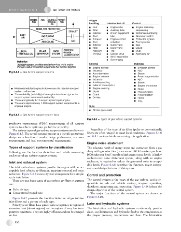
Fig 6.4.1 Gas turbine support systems
Aero-derivative Steam
Engine external Power augmentation
Industrial H 2 O
Auxiliary cooling Steam
Lube oil coolers(etc.) E n n i g e e n o l c s e r u s
Most unscheduled engine shutdowns are the result of a support E n n i g e e l c a n i n g Noise
system malfunction. Liquid Pressurization
The availability (reliability) of an engine is only as high as the Crank Fire protection
support system component availability. On-line Halon
There are typically 8–10 support systems per engine.
CO 2
There are approximately 1,000 support system components in
a typical engine. Solid
On-line (industrial)
Fig 6.4.2 Gas turbine support system facts
Fig 6.4.3 Types of gas turbine support systems
predictive maintenance (PDM) requirements of all support
systems to achieve optimum gas turbine reliability.
The various types of gas turbine support systems are shown in Regardless of the type of air filter (pulse or conventional);
Figure 6.4.3. The actual systems present in a specific gas turbine filters are often ‘staged’ to meet local conditions. Figures 6.4.6
design are a function of vendor design preferences, customer and 6.4.7 contain details concerning this application.
requirements and local environmental requirements.
Engine noise abatement
Types of support systems by classification The inherent result of energy input and extraction from a gas
Following are the function definition and details concerning along with gas velocities (in excess of 960 kilometers per hour
each type of gas turbine support system. [600 miles per hour]) result in high engine noise levels. A highly
sophisticated noise abatement system, along with an engine
Inlet and exhaust system enclosure, is required to reduce the generated noise to accept-
able levels. Figure 6.4.8 describes the function, major compo-
The inlet and exhaust systems provide the engine with an ac- nents and design features of this system.
ceptable level of inlet air filtration, moisture removal and noise
reduction. Figure 6.4.4 shows a typical arrangement for a simple Control and protection
cycle installation.
There are two basic types of gas turbine air filters in current The control system is the heart of the gas turbine, and is re-
use: sponsible for safe and reliable start-up, at-speed operation,
shutdown, monitoring and protection. Figure 6.4.9 defines the
- Pulse air type design objectives of the control system.
- Conventional staged type The major functions of the control system are shown in
Figure 6.4.10.
Figure 6.4.5 presents the function definition of gas turbine
inlet filters and a picture of each type.
Pulse type air filters have gained wide acceptance in regions of Lube and hydraulic systems
excessive dust (desert regions) and in regions of very low tem- The lubrication and hydraulic systems continuously provide
perature conditions. They are highly efficient and can be changed clean, cool lubrication and hydraulic fluid to the components at
on line. the proper pressure, temperature and flow. The lubrication
330