
Page 362 - Subyek Teknik Mesin - Forsthoffers Best Practice Handbook for Rotating Machinery by William E Forsthoffer
P. 362
Gas Turbine Best Practices Be st Practice 6.4
Function: Reduce noise to specified level at specified distances Function: identical to steam turbine/turbo-compressor –
from engine. Typical levels are: continuously provide cool, clean oil to bearings and control
90 DBA overall – 1 meter (3.3 ft) components at the proper pressure, temperature and flow rate.
55–65 DBA overall – 130 meters (400 ft) However, due to the high temperatures experienced in gas
Components: Inlet silencer turbines and engine design features, there are differences.
Engine compartment
Industrial types Aero-derivative types
Exhaust silencer
Comments: Rigid design Main pump engine driven Main pump engine driven
Corrosion proof elements (thru accessory gear box) (thru accessory gear box)
Emergency cool down Smaller, very compact
pump (D.C.) design
Fig 6.4.8 Engine noise abatement Compact design Use of synthetic oil
Guarded pipe (supply pipe Requirement of:
within drain pipe) Air/oil separator
Possible use of: Scavenge return oil pumps
Synthetic oil (high flash point)
Like steam turbines, gas turbines have similar control and
protection systems
In fact, third generation control systems are identical for steam Fig 6.4.12 Gas turbine lubrication and control systems
and gas turbines
However, due to high engine temperatures, gas turbine start-up
(heat-up) and shutdown (cool down) time must be accurately
controlled to prevent engine damage caused by:
Rubs
Rotor bow
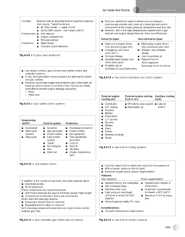
External engine External engine cooling Auxiliary cooling
cooling (air) (H Oorair) (H O)
2
2
Fig 6.4.9 Gas turbine control systems Combustor HP turbine case (jacket) Lube oil
H.P. turbine Atomization air coolers
Nozzles
Blades
Rotor/discs
Sequencing L.P. turbine
system Control system Protection Nozzles
Blades
Automated Governor Overspeed protection Discs
Start cycle Gas generator Power turbine Rotors
(starter) Power turbine Gas generator Bearing housings
Stop cycle Fuel control Train parameter Struts
system protection
Liquid Lube oil
Atomizing air Seal oil Fig 6.4.13 Gas turbine cooling systems
Gas Vibration
Dual fuel Engine temperature
(etc.)
Fig 6.4.10 Gas turbine control
Function: Inject H 2 O or steam into engine for the purpose of:
NOx emission reduction (25–42 ppm)
Increased engine power (power augmentation)
Features:
N O x e r d u o i t c n P o w r e a u g m e o i t a t n n
In addition to the normal components, aero-lube systems utilize:
Injected directly into combustor Injected down stream of
Scavenge pumps
Air/oil separators Self contained skids compressor
These components are required because: Stainless steel pipe Superheat requirements
Anti-friction bearings are used to minimize system flight weight High pressure centrifugal for steam 30°C (50°F)
Conventional atmospheric drains are not possible (sundyne or equal) for H 2 O Maximum 3–5% by mass
Oil/air mist from bearings must be: injection flow
Scavenged (drawn) back to reservoir Amount approximately 2% mass
Separated prior to return to reservoir
Both scavenge pumps and separators are engine driven via the Considerations:
auxiliary gear box Hot path maintenance requirements
Fig 6.4.11 Aero-derivative gas turbine lube oil systems Fig 6.4.14 Gas turbine injection systems
333