
Page 360 - Subyek Teknik Mesin - Forsthoffers Best Practice Handbook for Rotating Machinery by William E Forsthoffer
P. 360
Gas Turbine Best Practices Be st Practice 6.4
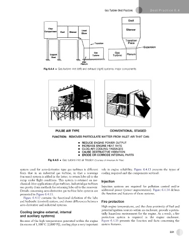
Fig 6.4.4 Gas turbine inlet (left) and exhaust (right) systems: major components
Fig 6.4.5 Gas turbine inlet air filtration (Courtesy of American Air Filter)
system used for aero-derivative type gas turbines is different role in engine reliability. Figure 6.4.13 presents the types of
from that in an industrial gas turbine, in that a scavenge cooling required and the components serviced.
(vacuum) system is added in the latter, to return lube oil to the
sump under flight conditions. This system is retained on me- Injection
chanical drive applications of gas turbines. Industrial gas turbines
use gravity drain methods for returning lube oil to the reservoir. Injection systems are required for pollution control and/or
Details concerning aero-derivative gas turbine lube systems are additional power (power augmentation). Figure 6.4.14 defines
presented in Figure 6.4.11. the function and features of these systems.
Figure 6.4.12 contains the functional definition of the lube
and hydraulic (control) system, and shows differences between Fire protection
aero-derivative and industrial systems.
High engine temperatures, and the close proximity of fuel and
potential ignition sources within an enclosure, provide a poten-
Cooling (engine external, internal
tially hazardous environment for the engine. As a result, a fire
and auxiliary systems) protection system is required in the engine enclosure.
Because of the high temperatures generated within the engine Figure 6.4.15 presents the function and facts concerning the
(in excess of 1,100 C [2,000 F]), cooling plays a very important system features.
331