
Page 363 - Subyek Teknik Mesin - Forsthoffers Best Practice Handbook for Rotating Machinery by William E Forsthoffer
P. 363
Be st Practice 6 .4 Gas Turbine Best Practices
Function: Quickly and effectively extinguish and confine On-line cleaning should be performed periodically and
engine fires. frequently because:
Protection Carbon dioxide All particles must be removed immediately in a uniform manner
mediums: Halon (limited use in future – impact on ozone to avoid destructive vibration.
layer) Cleaner injection rates and injection periods should be
System features: Multiple fire detectors minimized to prevent:
Medium control system Erosion
Dispenses medium and trips engine on Corrosion
confirmation of fire Cleaner composition must be confirmed to be satisfactory by
manufacturer to ensure:
Material and coating capability
Fig 6.4.15 Gas turbine fire protection systems Acceptable hot path component capability
Combustors
Nozzle, blade cooling passages
Entire cleaning procedure must be reviewed with engine
manufacturer.
Fig 6.4.17 Gas turbine cleaning systems on-line cleaning
Function: To remove air compressor blade deposits and to restore precautions
power output and efficiency in a safe and reliable manner.
Options: Crank – performed at low (crank) speeds
H 2 O/glycol/detergent
H 2 O/glycol 1
On-line – performed at usually idle speed
H 2 O/glycol 2
H 2 O/glycol/detergent
Solid particle (walnut shells, catalyst) heavy duty only
1
Notes: Manufacturer must be consulted regarding acceptable
cleaning procedures.
2
Must be used where operation below approximately 40° is possible.
Fig 6.4.16 Gas turbine internal component cleaning systems
Internal component cleaning
Available power can be significantly reduced by engine fouling
(accumulation of dirt on air compressor blades and stators).
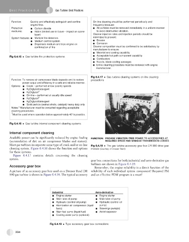
Most gas turbines incorporate some type of crank and/or on-line Fig 6.4.18 The gas turbine accessory gear box DR 990 drive gear
cleaning system. Figure 6.4.16 shows the function and options module (Courtesy of Dresser Rand)
for these systems.
Figure 6.4.17 contains details concerning the cleaning
system.
gear box connections for both industrial and aero-derivative gas
turbines are shown in Figure 6.4.19.
Accessory gear box Remember, the engine reliability is a direct function of the
A picture of an accessory gear box used on a Dresser Rand DR reliability of each individual system component! Required PM
990 gas turbine is shown in Figure 6.4.18. The typical accessory and an effective PDM program is a must!
Industrial Aero-derivative
Engine starter Engine starter
Main lube oil pump Main lube oil pump
Hydraulic (control oil pump) Hydraulic (control oil
Atomization air compressor (liquid pump)
fuels) Scavenge pump(s)
Main fuel pump (liquid fuel) Air/oil separator
Cooling water pump (optional)
Fig 6.4.19 Type accessory gear box connections
334