
Page 364 - Subyek Teknik Mesin - Forsthoffers Best Practice Handbook for Rotating Machinery by William E Forsthoffer
P. 364
Gas Turbine Best Practices Be st Practice 6.5
Best
Best
Best Practice 6.5Practice 6.5Practice 6.5
Use tilting pad radial bearings and not ‘lemon or offset If bearing instabilities are experienced, a possible modification is to
sleeve anti-whirl type bearings’ to positively eliminate rotate the major axis of the ellipse to provide sufficient oil film stiffness
vibration instabilities. at the load angle. This procedure takes time and must be repeated in
Tilting pad radial bearings provide vibration stability at any load the field each time the machine is disassembled.
angle. If the above procedure is not successful, installation of multi lobe or
tilting pad bearings will be required. This procedure will be time con-
Lemon bore (elliptical) or offset sleeve (to achieve an elliptical ar-
suming and can delay tests for months.
rangement) bearings do not eliminate vibration instabilities if the load
angle lies in the major axis of the ellipse, since the oil film stiffness in
this region may not be sufficient to prevent vibration instabilities. Benchmarks
This best practice has been used since the early 1980s when offset
bearings were required to be changed to multi lobe bearings during the
Lessons Learned FAT. Delivery delay was three months. It should be noted that the
Lemon bore or offset sleeve bearings have caused ex- vendor made the modified multi lobe bearing standard on all sub-
tended FAT periods necessary to modify bearing split line sequent turbines. Use of this best practice has resulted in trouble free
orientation or changes to three or four lobe or tilt pad turbine operation and reliabilities 99.5% and higher.
bearings.
F
B.P. 6.5. Supporting Material P ¼ A
Where: P ¼ Wedge support pressure (P.S.I.)
Hydrodynamic bearings F ¼ Total bearing loads (static and dynamic)
A ¼ Projected bearing area (A PROJECTED )
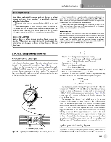
Hydrodynamic bearings support the rotor using a liquid wedge A PROJECTED ¼ L d
formed by the motion of the shaft (see Figure 6.5.1). Where: L ¼ Bearing axial length
Oil enters the bearing at supply pressure values of typically d ¼ Bearing diameter
103-138kPa (15-20 psig). The shaft acts like a pump which As an example, a 4" diameter bearing with an axial length of
2
increases the support pressure to form a wedge. The pressure of 2" (L/d ¼ 0.5) would have A PROJECTED ¼ 8in .
the support liquid (usually mineral oil) is determined by the area If the total of static and dynamic forces acting on the bearing
of the bearing by the relationship: are 1600 lbs force, the pressure of the support wedge is:
1600 Lb FORCE
P ¼ 2
8in
¼ 1; 380 kPa ð200 PSIÞ:
The maximum desired design wedge pressure for oil is ap-
proximately 3,450kPa (500 psi). However, it has been common
practice to limit hydrodynamic bearing loads to approximately
1,725kPa (250 psi) in compressor applications. Figure 6.5.2 is
a side view of a simple hydrodynamic bearing showing the
dynamic load forces.
The primary force is the load, which acts in the vertical
direction for horizontal bearings. However, the fluid tangential
force can become large at high shaft speeds. The bearing load
vector then is the resultant of the load force and fluid tangential
force. The fluid radial force opposes the load vector and thus
supports the shaft. It has been demonstrated that the average
velocity of the oil flow is approximately 47-52% of the shaft
velocity. The fluid tangential force is proportional to the journal
oil flow velocity. If the fluid tangential force exceeds the load
force, the shaft will become unstable and will be moved around
the bearing shell. This phenomenon is known as oil whirl.
Hydrodynamic bearing types
Regardless of the type of hydrodynamic bearing, all its surfaces
Fig 6.5.1 Hydrodynamic lubrication (Courtesy of Bently Nevada Corp.) are lined with a soft, surface material made of a composition of
335