
Page 502 - Subyek Teknik Mesin - Forsthoffers Best Practice Handbook for Rotating Machinery by William E Forsthoffer
P. 502
Pump Mechanical Seal Flush Best Practices Be st Practice 8.3
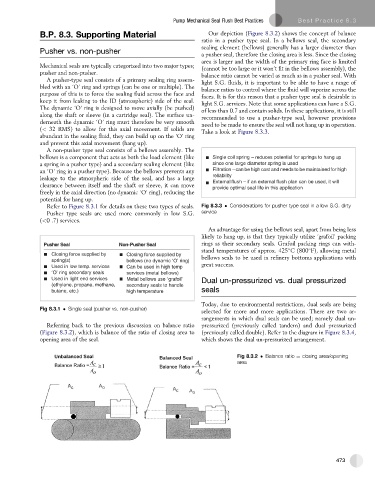
B.P. 8.3. Supporting Material Our depiction (Figure 8.3.2) shows the concept of balance
ratio in a pusher type seal. In a bellows seal, the secondary
sealing element (bellows) generally has a larger diameter than
Pusher vs. non-pusher
a pusher seal, therefore the closing area is less. Since the closing
area is larger and the width of the primary ring face is limited
Mechanical seals are typically categorized into two major types; (cannot be too large or it won’t fit in the bellows assembly), the
pusher and non-pusher. balance ratio cannot be varied as much as in a pusher seal. With
A pusher-type seal consists of a primary sealing ring assem- light S.G. fluids, it is important to be able to have a range of
bled with an ‘O’ ring and springs (can be one or multiple). The balance ratios to control where the fluid will vaporize across the
purpose of this is to force the sealing fluid across the face and faces. It is for this reason that a pusher type seal is desirable in
keep it from leaking to the ID (atmospheric) side of the seal. light S.G. services. Note that some applications can have a S.G.
The dynamic ‘O’ ring is designed to move axially (be pushed) of less than 0.7 and contain solids. In these applications, it is still
along the shaft or sleeve (in a cartridge seal). The surface un-
recommended to use a pusher-type seal, however provisions
derneath the dynamic ‘O’ ring must therefore be very smooth need to be made to ensure the seal will not hang up in operation.
(< 32 RMS) to allow for this axial movement. If solids are
Take a look at Figure 8.3.3.
abundant in the sealing fluid, they can build up on the ‘O’ ring
and prevent this axial movement (hang up).
A non-pusher type seal consists of a bellows assembly. The
bellows is a component that acts as both the load element (like Single coil spring – reduces potential for springs to hang up
a spring in a pusher type) and a secondary sealing element (like since one large diameter spring is used
an ‘O’ ring in a pusher type). Because the bellows prevents any Filtration – can be high cost and needs to be maintained for high
leakage to the atmospheric side of the seal, and has a large reliability
External fl ush – if an external fl ush plan can be used, it will
clearance between itself and the shaft or sleeve, it can move provide optimal seal life in this application
freely in the axial direction (no dynamic ‘O’ ring), reducing the
potential for hang up.
Refer to Figure 8.3.1 for details on these two types of seals. Fig 8.3.3 Considerations for pusher type seal in a low S.G. dirty
Pusher type seals are used more commonly in low S.G. service
(<0 .7) services.
An advantage for using the bellows seal, apart from being less
likely to hang up, is that they typically utilize ‘grafoil’ packing
P u s h r e S e l a N o - n P u s h r e S e l a rings as their secondary seals. Grafoil packing rings can with-
stand temperatures of approx. 425 C (800 F), allowing metal
Closing force supplied by Closing force supplied by
spring(s) bellows (no dynamic ‘O’ ring) bellows seals to be used in refinery bottoms applications with
Used in low temp. services Can be used in high temp great success.
‘O’ ring secondary seals services (metal bellows)
Used in light end services Metal bellows use ‘grafoil’ Dual un-pressurized vs. dual pressurized
(ethylene, propane, methane, secondary seals to handle
butane, etc.) high temperature seals
Today, due to environmental restrictions, dual seals are being
Fig 8.3.1 Single seal (pusher vs. non-pusher)
selected for more and more applications. There are two ar-
rangements in which dual seals can be used; namely dual un-
Referring back to the previous discussion on balance ratio pressurized (previously called tandem) and dual pressurized
(Figure 8.3.2), which is balance of the ratio of closing area to (previously called double). Refer to the diagram in Figure 8.3.4,
opening area of the seal. which shows the dual un-pressurized arrangement.
Fig 8.3.2 Balance ratio ¼ closing area/opening
area
473