Page 504 - Subyek Teknik Mesin - Forsthoffers Best Practice Handbook for Rotating Machinery by William E Forsthoffer
P. 504
Pump Mechanical Seal Flush Best Practices  Be st Practice 8.3
                Teflon (PTFE), PEEK and Grafoil packing have the highest
              temperature resistance, but are stiff, and poor secondary sealing  HC service with no known solid particles and temperature under
              elements compared to ‘O’ rings (‘O’ rings should be used where  150°C (300°F)
              the application allows).                                Assuming satisfactory vapor margin (approximately 345 kPa
                                                                      [50 psi] above vapor pressure) in seal chamber a Plan 11 would
                                                                      be the optimal choice.
              Seal faces                                              A vertical pump application would require venting of the seal
                                                                      chamber back to suction if possible (Plan 13 or 14).
              Seal face materials also need to be selected to be compatible  A Plan 52, 53 or 54 (53 or 54 preferred) would be recommended
              with the sealing fluid, however there is another reason. If you  in low S.G. ( < 0.7) services.
              recall our discussion on face generated heat, you will remember
              the term ‘f’ (coefficient of friction). This term describes the
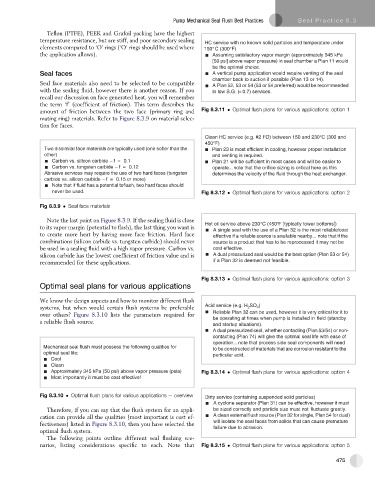
              amount of friction between the two face (primary ring and  Fig 8.3.11   Optimal flush plans for various applications: option 1
              mating ring) materials. Refer to Figure 8.3.9 on material selec-
              tion for faces.

                                                                    Clean HC service (e.g. #2 FO) between 150 and 230°C (300 and
                                                                    450°F)
                Two dissimilar face materials are typically used (one softer than the   Plan 23 is most ef fi cient in cooling, however proper installation
                other)                                                and venting is required.
                  Carbon vs. silicon carbide – f  =  0.1              Plan 21 will be suf fi cient in most cases and will be easier to
                  Carbon vs. tungsten carbide – f  =  0.12            operate ... note that the ori fi ce sizing is critical here as this
                Abrasive services may require the use of two hard faces (tungsten   determines the velocity of the fl uid through the heat exchanger.
                carbide vs. silicon carbide – f  =  0.15 or more)
                  Note that if fluid has a potential toflash, two hard faces should
                  never be used.                                   Fig 8.3.12   Optimal flush plans for various applications: option 2

              Fig 8.3.9   Seal face materials
                Note the last point on Figure 8.3.9. If the sealing fluid is close
                                                                    Hot oil service above 230°C (450°F [typically tower bottoms])
              to its vapor margin (potential to flash), the last thing you want is
                                                                       A single seal with the use of a Plan 32 is the most reliable/cost
              to create more heat by having more face friction. Hard face  effective if a reliable source is available nearby... note that if the
              combinations (silicon carbide vs. tungsten carbide) should never  source is a product that has to be reprocessed it may not be
              be used in a sealing fluid with a high vapor pressure. Carbon vs.  cost effective.
              silicon carbide has the lowest coefficient of friction value and is  A dual pressurized seal would be the best option (Plan 53 or 54)
              recommended for these applications.                      if a Plan 32 is deemed not feasible.

                                                                   Fig 8.3.13   Optimal flush plans for various applications: option 3
              Optimal seal plans for various applications

              We know the design aspects and how to monitor different flush
              systems, but when would certain flush systems be preferable  Acid service (e.g. H 2 SO 4 )
                                                                      Reliable Plan 32 can be used, however it is very critical for it to
              over others? Figure 8.3.10 lists the parameters required for
                                                                      be operating at times when pump is installed in field (standby
              a reliable flush source.
                                                                      and startup situations).
                                                                      A dual pressurized seal, whether contacting (Plan 53/54) or non-
                                                                      contacting (Plan 74) will give the optimal seal life with ease of
                                                                      operation... note that process side seal components will need
               Mechanical seal fl ush must possess the following qualities for   to be constructed of materials that are corrosion resistant to the
               optimal seal life:                                     particular acid.
                  Cool
                  Clean
                  Approximately 345 kPa (50 psi) above vapor pressure (psia)   Fig 8.3.14   Optimal flush plans for various applications: option 4
                  Most importantly it must be cost effective!


              Fig 8.3.10   Optimal flush plans for various applications e overview  Dirty service (containing suspended solid particles)
                                                                       A cyclone separator (Plan 31) can be effective, however it must
                Therefore, if you can say that the flush system for an appli-  be sized correctly and particle size must not fluctuate greatly.
              cation can provide all the qualities (most important is cost ef-  A clean externalflush source (Plan 32 for single, Plan 54 for dual)
              fectiveness) listed in Figure 8.3.10, then you have selected the  will isolate the seal faces from solids that can cause premature
                                                                       failure due to abrasion.
              optimal flush system.
                The following points outline different seal flushing sce-
              narios, listing considerations specific to each. Note that  Fig 8.3.15   Optimal flush plans for various applications: option 5

                                                                                                               475

