
Page 503 - Subyek Teknik Mesin - Forsthoffers Best Practice Handbook for Rotating Machinery by William E Forsthoffer
P. 503
Be st Practice 8 .3 Pump Mechanical Seal Flush Best Practices
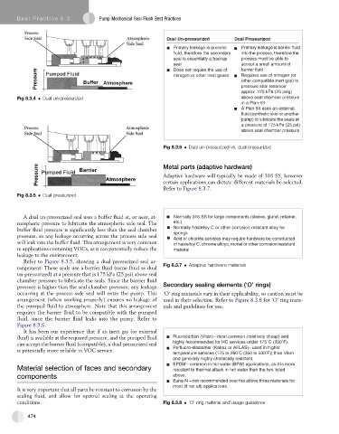
Dual Un-pressurized Dual Pressurized
Primary leakage is process Primary leakage is barrier fluid
fl uid, therefore the secondary into the process, therefore the
seal is essentially a backup process must be able to
seal accept a small amount of
Does not require the use of barrier fl uid
nitrogen or other inert gases Requires use of nitrogen (or
other compatible inert gas) to
pressure seal reservoir
approx .175 kPa (25 psig)
Fig 8.3.4 Dual un-pressurized above seal chamber pressure
in a Plan 53
A Plan 54 uses an external
fl uid (synthetic skid or another
pump) to lubricate the seals at
a pressure of 175 kPa (25 psi)
above seal chamber pressure
Fig 8.3.6 Dual un-pressurized vs. dual pressurized
Metal parts (adaptive hardware)
Adaptive hardware will typically be made of 316 SS, however
certain applications can dictate different materials be selected.
Refer to Figure 8.3.7.
Fig 8.3.5 Dual pressurized
A dual un-pressurized seal uses a buffer fluid at, or near, at- Normally 316 SS for large components (sleeve, gland, retainer,
mospheric pressure to lubricate the atmospheric side seal. The etc.)
buffer fluid pressure is significantly less than the seal chamber Normally hastelloy C or other corrosion resistant alloy for
pressure, so any leakage occurring across the process side seal springs
Acid or chloride services may require hardware be constructed
will leak into the buffer fluid. This arrangement is very common of hastelloy C, chrome alloys, monel or other corrosion resistant
in applications containing VOCs, as it can potentially reduce the material
leakage to the environment.
Refer to Figure 8.3.5, showing a dual pressurized seal ar-
Fig 8.3.7 Adaptive hardware materials
rangement. These seals use a barrier fluid (same fluid as dual
un-pressurized) at a pressure that is 175 kPa (25 psi) above seal
chamber pressure to lubricate the seals. Since the barrier fluid
pressure is higher than the seal chamber pressure, any leakage Secondary sealing elements (‘O’ rings)
occurring at the process side seal will enter the pump. This ‘O’ ring materials vary in their applicability, so caution must be
arrangement (when working properly) ensures no leakage of used in their selection. Refer to Figure 8.3.8 for ‘O’ ring mate-
the pumped fluid to atmosphere. Note that this arrangement rials and guidelines for use.
requires the barrier fluid to be compatible with the pumped
fluid, since the barrier fluid leaks into the pump. Refer to
Figure 8.3.6.
It has been our experience that if an inert gas (or external
fluid) is available at the required pressure, and the pumped fluid Fluorocarbon (Viton) – most common (relatively cheap) and
°
°
can accept the barrier fluid (compatible), a dual pressurized seal highly recommended for HC services under 175 C (350 F).
Per fl uoro-elastomer (Kalrez or AFLAS) – used in higher
is potentially more reliable in VOC service. ° °
temperature services (175 to 260 C (350 to 500 F)) than Viton
and generally highly chemically resistant.
EPDM – common in hot water (BFW) applications, as it is more
Material selection of faces and secondary resistant to thermal attack in hot water than the two listed
components above.
Buna-N – not recommended over the above three materials for
most (if not all) applications.
It is very important that all parts be resistant to corrosion by the
sealing fluid, and allow for optimal sealing at the operating
conditions. Fig 8.3.8 ‘O’ ring material and usage guidelines
474