
Page 508 - Subyek Teknik Mesin - Forsthoffers Best Practice Handbook for Rotating Machinery by William E Forsthoffer
P. 508
Pump Mechanical Seal Flush Best Practices Be st Practice 8.7
The most critical of these characteristics is the fluid’s vapor
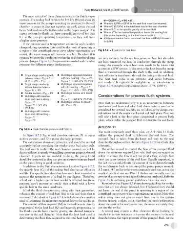
pressure. The sealing fluid needs to be 345 kPa (50 psi) above its M = Q/(500 C SG T)
P
vapor pressure (at the pump’s operating temperature) in the seal Where M (LPM or GPM) is the seal fluid massflow required
chamber to ensure it does not vaporize too early across the seal Where Q (BTU/hr) is the total heat load in the seal chamber
faces. Seal vendors refer to this value as the ‘vapor margin’.Itis Where S.G. is the specific gravity of the seal fluid
a great concern for fluids that have a specific gravity of less than Where T is the desired temperature rise of the sealingfluid
0.7 at the pump’s operating temperature, as they will have (this varies depending on the fluid characteristics)
500 is a conversion factor to convert the flow to GPM (125 used
a higher vapor pressure. for LPM)
If the pressure and/or temperature within the seal chamber
changes during operation (this could be the result of operating in
a region of the centrifugal pump curve where vaporization can Fig 8.7.4 Equation for seal flow
occur), the vapor margin will become smaller. Therefore it is
essential to know the conditions within the seal chamber during not only accounts for the seal face generated heat but also adds
process changes. Figure 8.7.3 represents estimated seal chamber any heat generated via heat, or conduction through the pump
pressures for different pump configurations. casing. An example where heat soak needs to be taken into
account is a BFW service. In this service the heat from the pump
fluid is transmitted through the shaft to the seal. In addition,
Single stage overhung with Multistage opposed impellers heat will also be transferred through the casing to the seal fluid.
balance holes – P SC =P1 with new bushing – P SC1 =P1 The heat soak value is an estimate, and varies between
(0.15 (P2 P1)) P SC2 = P1 525 kPa (75 PSI) seal vendors. It typically is negligible in the calculation in
Single stage overhung Multistage opposed impellers Figure 8.7.4 except in applications above 177 C (350 F).
without balance holes – with old bushing – P SC1 =P1
P SC =.8 P2 P SC2 = P1 (0.5 (P2 P1))
Double suction – P SC =P1 Multistage vertical with bleed
Multistage with balance off – Considerations for process flush systems
drum and new bushing – P SC = P1 525 kPa (75 PSI)
P SC1 =P1 Multistage vertical no bleed Now that we understand why it is so important to lubricate
P SC2 = P1 525 kPa off – P SC =P2 mechanical seal faces and what fluid characteristics need to be
(75 PSI) considered for optimal seal life, we will discuss the design con-
Multistage with balance
drum and old bushing – siderations for all the major mechanical seal flush plans. First, we
P SC1 =P1 will take a look at the flush plans categorized as process flush
P SC2 =P2 plans, which utilize the pumped fluid to lubricate the seal faces.
API Plan 11
Fig 8.7.3 Seal chamber pressure estimations
The most commonly used flush plan, an API Plan 11 flush,
In Figure 8.7.3 P SC is seal chamber pressure, P1 is pump utilizes the pumped fluid to lubricate the seal faces. The
suction pressure, and P2 is pump discharge pressure. pumped fluid is taken from discharge and sent to the seal
The calculations shown are estimates, and should be verified chamber through an orifice. Refer to Figure 8.7.5 for a flush plan
accurately before consulting the vendor about bad actor seals. schematic.
The best way to confirm the seal chamber pressure, as will be The orifice is used to control the flow of the pumped fluid
discussed later, is simply by installing a pressure gauge in the seal above the minimum required flow rate. Seal vendors require an
chamber. If ports are not available to do so, the pump OEM orifice to ensure the flow is not too great either, as high flow
should be contacted as they can give an accurate estimate based rates can cause erosion of the seal faces. Equally important, is
on the pump being in good condition. the fact that an orifice limits the amount of recirculation through
In addition to the fluid characteristics listed in Figure 8.7.2, the seal chamber back to the pump (the pump pumps money).
the specific heat (C P ) of the sealing fluid also has an effect on A 3 mm (1/8") orifice is the most commonly used size, as it is the
seal life. The specific heat describes how much heat is needed to smallest practical size and Plan 11 flushes are normally used in
increase the temperature of a fluid by one degree. Therefore, services that are easy to seal (good lubricating qualities). Refer to
a fluid with a higher specific heat would be affected less (tem- Figure 8.7.6, outlining general guidelines for orifice sizes.
perature won’t increase as much) than a fluid with a lower Remember that Figure 8.7.6 just shows guidelines for orifice
specific heat in the same conditions. sizes that are not always followed, but if followed they should
All of the fluid characteristics, along with heat generation, not harm the seal if the pump is operating in a region of the
influence the amount of seal fluid flow to the seal faces that is centrifugal pump curve where vaporization can occur. Note that
necessary. Take a look at Figure 8.7.4, which shows the equation orifice sizing does not give an exact flow, due to the system
used to determine the minimum required flow to the seal faces. friction (piping, coolers, etc.), therefore the more information
The amount of flow required (M) to the seal faces is directly about the system the seal vendor has, the more accurately they
proportional to the heat load (Q) and inversely proportional to can size the orifice.
the fluid’s specific heat, specific gravity, and desired tempera- A vendor may require a close clearance throat bushing be
ture rise in the seal chamber. Note that the heat load used in installed in certain instances to increase the pressure in the seal
determining the flush flow required is the total heat load. This chamber above the vapor pressure of the pumped fluid. As the
479